August 30, 2023
What Is a Netlist? Understanding the Basics of Electronic Design Automation

A netlist is essentially a textual representation of an electronic circuit. It describes the connectivity between different components, such as transistors, resistors, and capacitors, without necessarily detailing their physical arrangement. Think of it as the "source code" for a circuit, providing the essential information needed to understand how the circuit functions.
In circuit design, netlists serve as the intermediary between the schematic and the physical layout. Once a schematic is complete, it gets converted into a netlist, which can then be used for simulation, analysis, and eventually, physical layout generation.
To further understand the concept, consider a netlist as akin to a recipe in cooking. The recipe lists the ingredients (components) and explains how to combine them (connectivity), but it doesn't tell you how to physically arrange them on the plate.
In circuit design, a netlist acts as the blueprint for hardware implementation. It specifies how components are interconnected, thereby defining the circuit's functionality.
Netlists are crucial for various stages of hardware development, including simulation for performance analysis, logical synthesis for gate-level representation, and physical synthesis for layout generation.
An inaccurate or inefficient netlist can lead to hardware that doesn't function as intended, costing both time and resources. Therefore, generating and verifying an accurate netlist is a critical step in the design process.
Netlists can come in various formats, such as SPICE for circuit simulation and EDIF for interchange between different EDA tools.
A schematic netlist is derived directly from a circuit schematic and is more human-readable. In contrast, a structural netlist is a lower-level representation that describes the circuit in terms of gates and flip-flops.
Choosing the right format is crucial as it impacts the tools you can use for simulation and synthesis, thereby affecting the overall efficiency and accuracy of the design process.
An FPGA netlist describes the configuration and interconnection of logic blocks within an FPGA (Field-Programmable Gate Array). It is specifically tailored for the architecture of the FPGA in use.
An RTL netlist describes the circuit at the register-transfer level, focusing on how data moves between registers and how the logical operations on the data occur.This could be defined in hardware definitions (HDLs) like Verilog or VHDL.
FPGA netlists are essential for FPGA design and simulation, while RTL netlists are crucial for high-level synthesis and system-level descriptions.
An RTL netlist provides a high-level abstraction of the circuit, making it easier to understand and optimize the design for specific objectives like speed or power consumption.
Unlike schematic or structural netlists, RTL netlists allow for a more abstract representation of the circuit, focusing on data flow rather than specific gates or components.
RTL netlists are invaluable for system-level simulations and verifications, as they allow designers to test how individual components interact within the larger system.
In conclusion, netlists serve as the linchpin in the complex world of electronic circuit design, functioning as the textual blueprint that outlines the vital connections among various passive and active components like transistors, resistors, capacitors, and integrated circuits. They bridge the gap between the conceptual world of schematics and the concrete physical layouts, playing an important role at multiple stages, from simulation and logical synthesis to the generation of the final hardware layout. Their formats may vary, with options like SPICE for circuit simulation and EDIF for tool interchange, each bringing their own set of capabilities and limitations.
Specialized netlists, such as FPGA and RTL netlists, address specific design needs and provide varying levels of abstraction to better suit project objectives. An accurate and efficiently-structured netlist is not just a nice-to-have but a necessity, as errors can lead to functional issues in the hardware, costing time and resources. Understanding the intricacies of netlists, therefore, is not merely an academic exercise but a practical necessity for anyone involved in PCB design.


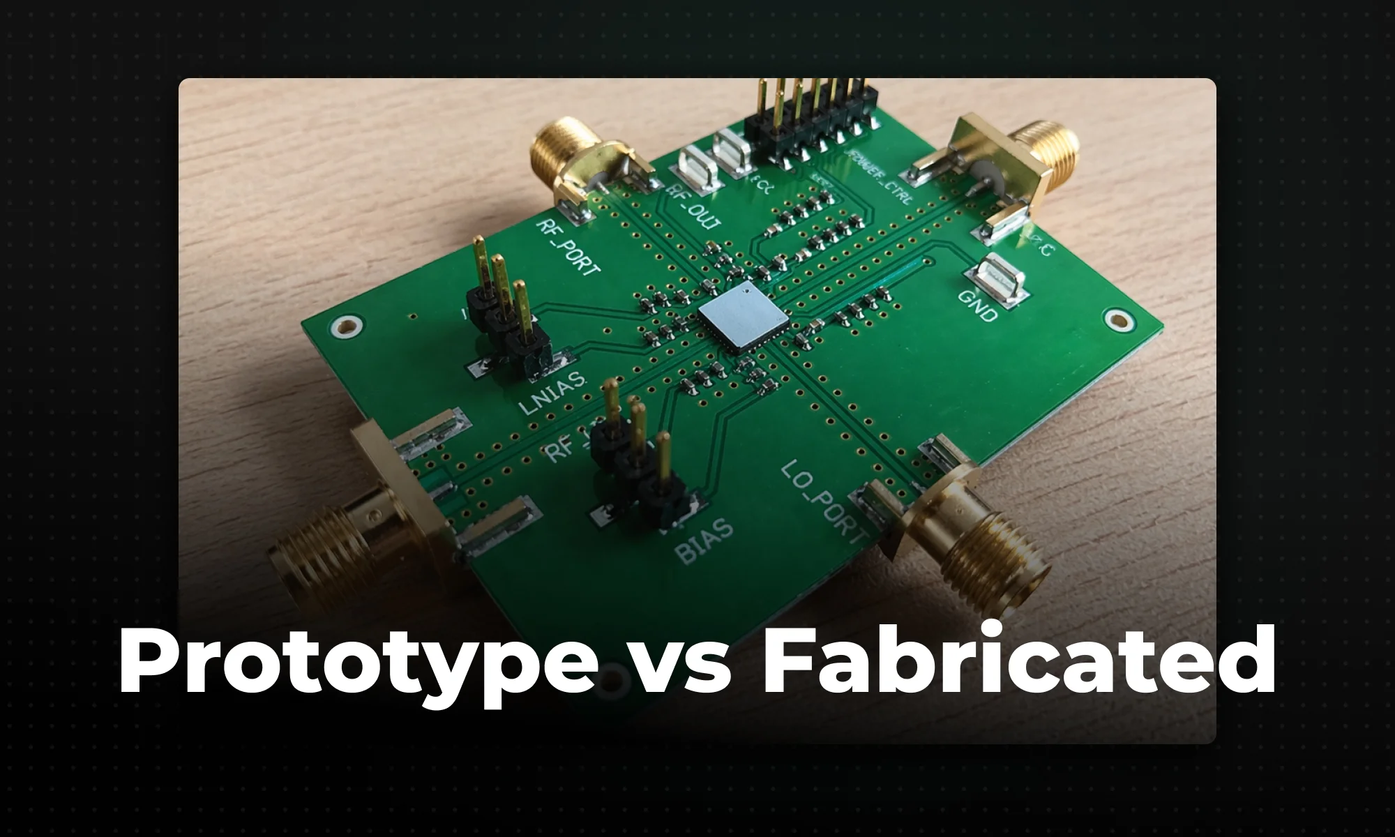
A practical guide to when hardware teams should use low-volume PCB prototyping to validate a design versus full-scale fabrication to scale production, and how to transition between the two without costly mistakes.
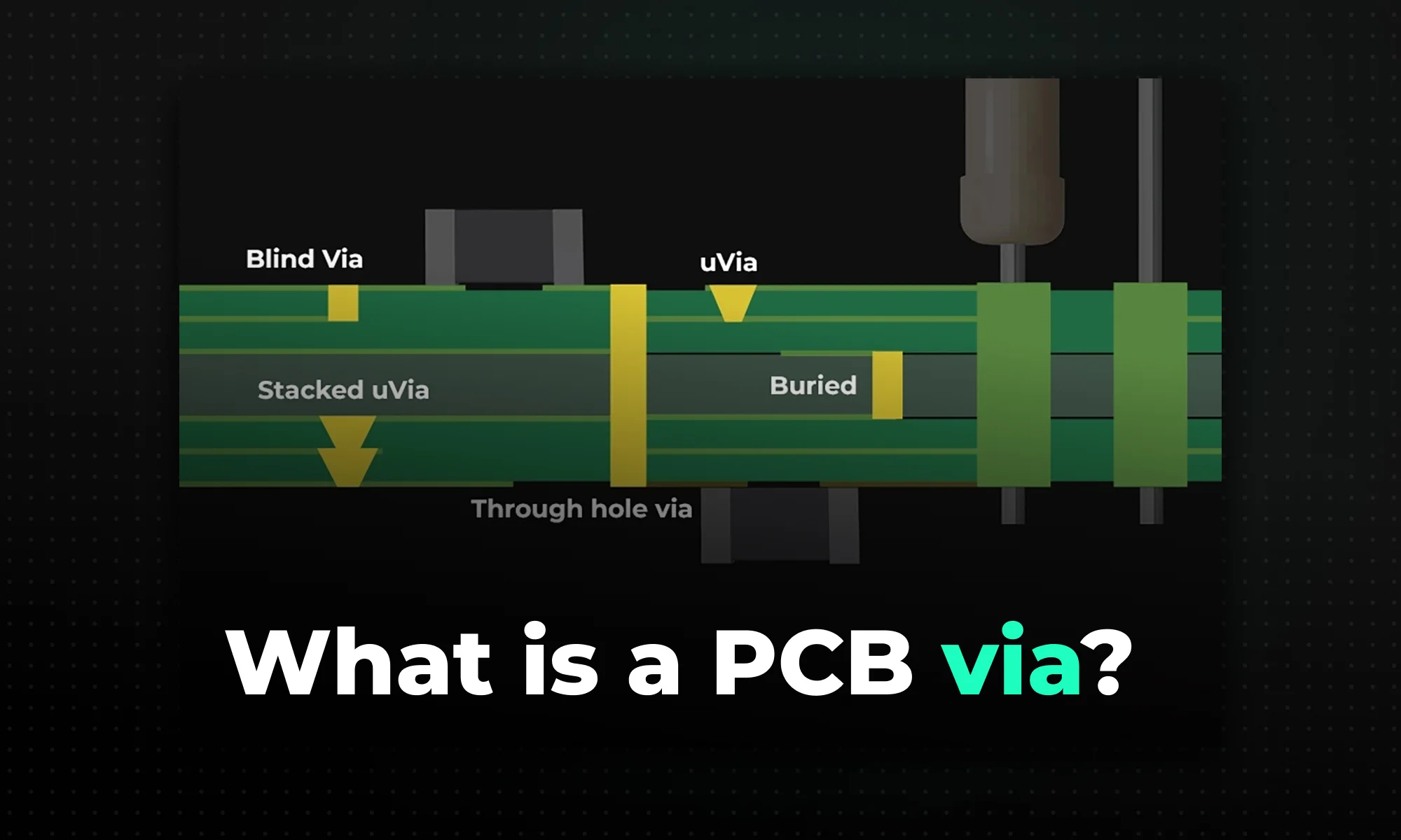
A practical guide to the four main PCB via types — through-hole, blind, buried, and microvia — covering how each is fabricated, their cost and signal-integrity trade-offs, and when to use them based on layer count, BGA pitch, and routing density.
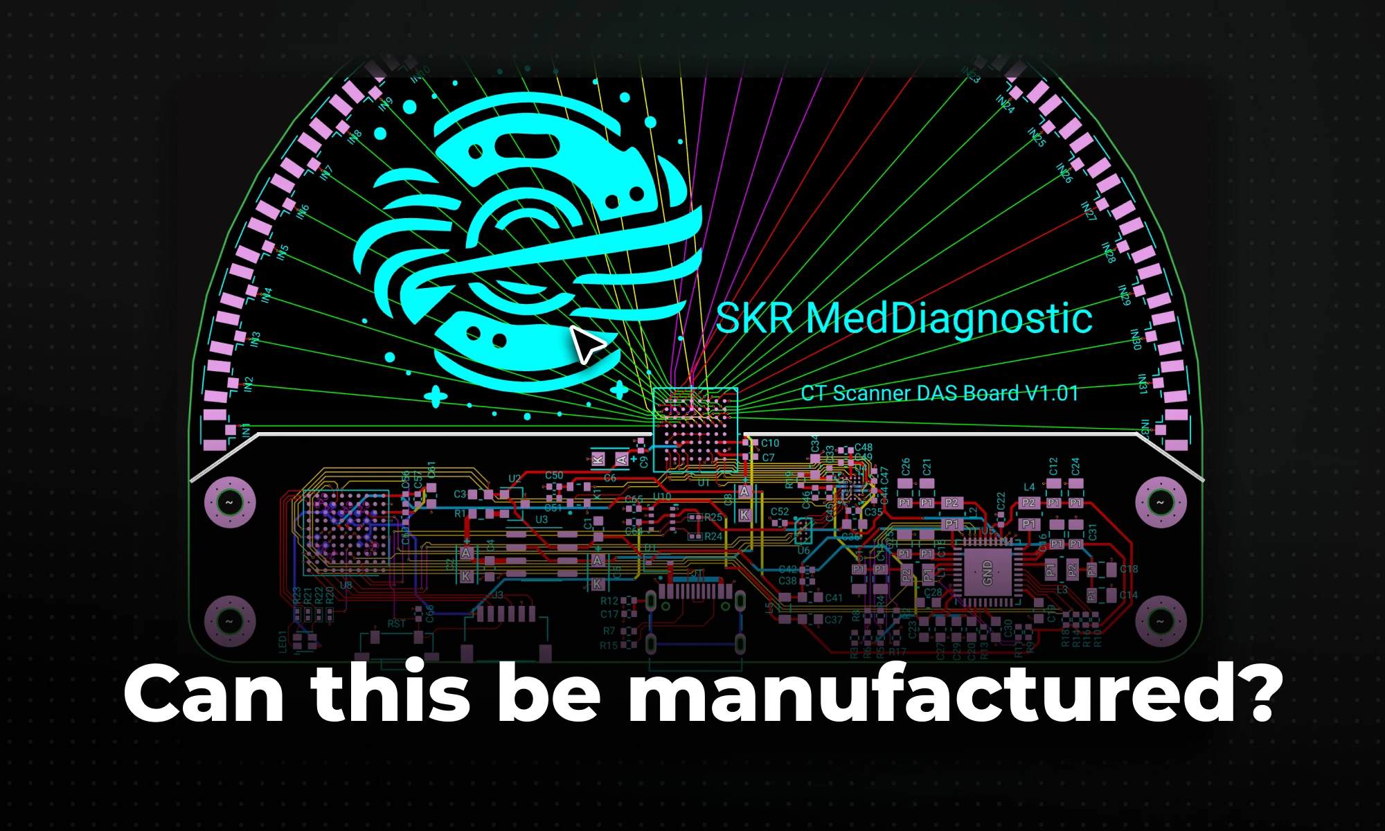
Learn PCB design for manufacturability (DFM) guidelines, rules, and common issues to ensure your circuit boards can be reliably produced.
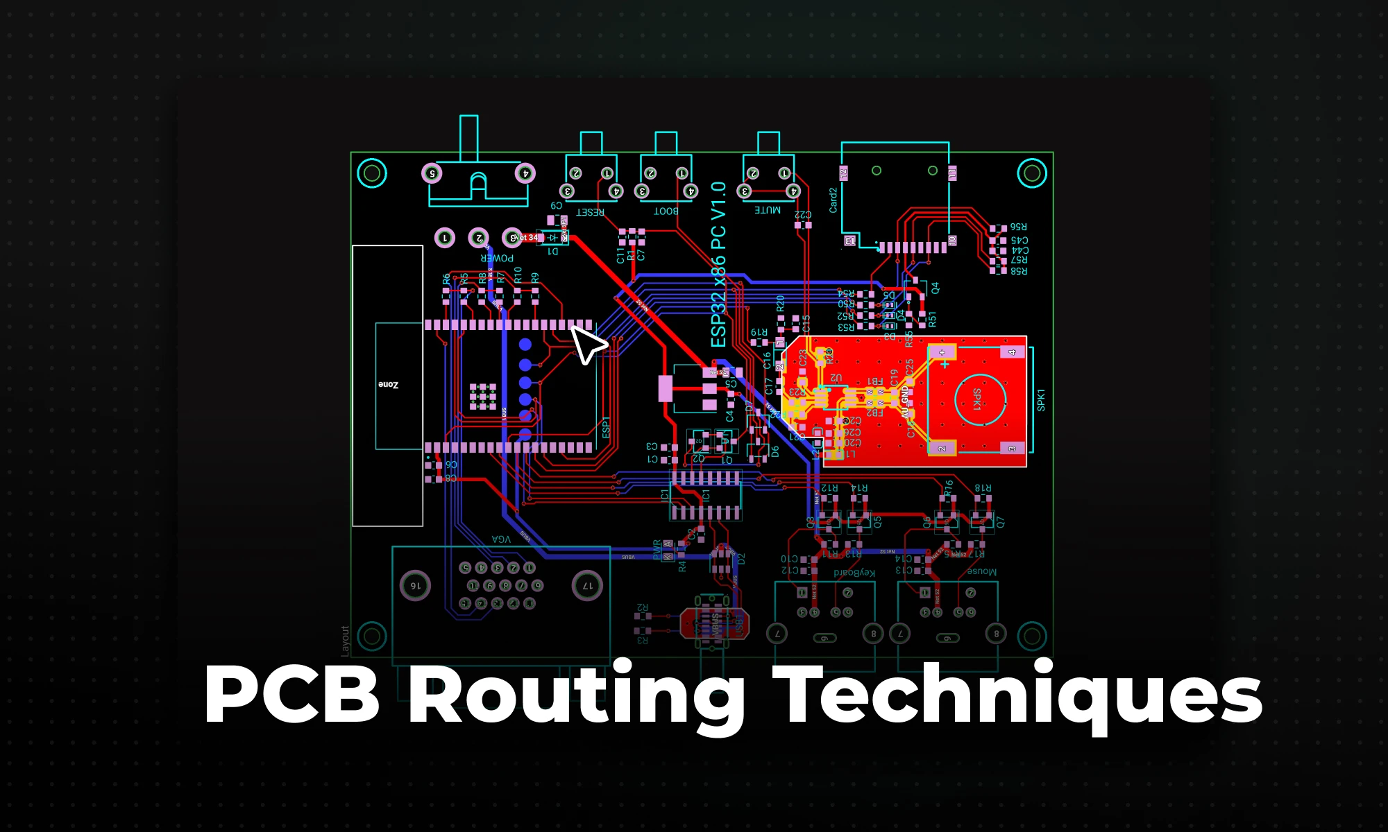
Learn the best PCB routing techniques for clean circuit board layouts, including trace routing tips, differential pair routing, and layout best practices.

Whether you're migrating from popular EDA applications or starting fresh, mastering high speed PCB design has never been more intuitive. Flux enables teams to design, simulate, and route with real-time AI assistance, so you can spin your next high-speed board with total confidence.

DRC is an automated process that checks your PCB layout against manufacturing and electrical constraints, catching errors like trace spacing and drill sizes before fabrication. Modern tools run this in real-time during design, while older ones batch-check at the end, often producing overwhelming error lists.

Whether you are exploring “What is a PCB?” for the first time or moving into advanced hardware engineering, modern tools make the process easier than ever. With Flux's AI-assisted platform, you can skip the steep learning curve of popular ECAD applications and design collaboratively directly in your browser. Once your board is routed and ready for fabrication, Flux's built-in supply chain features connect you directly with worldwide distributors to source parts instantly. Sign up for free today and start building!

Flux brings circuit simulation to wherever you are in the design process. Start from a prompt when you have no schematic, or let Flux analyze your existing design automatically.