March 20, 2026
Simulate Circuits with a Prompt
Share

Flux now has built-in circuit simulation, and your AI design assistant knows how to use it.
If you've ever designed a circuit board, you know the feeling. You finish your schematic, send it off for fabrication, wait for the boards to arrive, and then hold your breath. Will it work? Did you get the filter cutoff right? Is that decoupling cap actually sized correctly?
For most of hardware design history, the answer has been: build it and find out.
Simulation was always supposed to solve this. And technically, it can. SPICE has been around for decades. But in practice, simulation has been so cumbersome to set up that most engineers skip it entirely. Even some of the best-resourced hardware teams in the world have left simulation on the table because the overhead just isn't worth it for everyday design decisions.
That changes today.
We're introducing circuit simulation built directly into Flux. Describe what you want to simulate in plain language through the Flux AI chat, and Flux handles the rest: building the netlist, configuring the analysis, running the simulation, and returning charts with clear explanations.
No setup wizard. No exporting netlists. No switching tools.
Two ways to start:
From a prompt. Don't even have a schematic yet? Just describe the circuit and what you want to measure.
You: "Simulate a first-order RC low-pass filter with a 10 kΩ resistor and 10 nF capacitor. Generate the bode plot and find the -3 dB cutoff frequency."
Try this prompt

Flux: Runs an AC sweep, returns the bode plot, reports the -3 dB point at ~1.59 kHz, and confirms it matches the theoretical value of 1/(2πRC).
One sentence in, full analysis out.
From your schematic. Already have a design in progress? Even better. Flux pulls context from your parts, net connections, and datasheets to build the simulation automatically. You don't need to export anything or set up a separate project. Just ask.

You: "Simulate the voltage across C3. Show me the output ripple voltage in a plot.
Check the actual project.

Flux: Uses the components and connections already in your design, runs the analysis, and returns results without you specifying a single component value.
Your schematic is the test bench.
The simulator handles the kinds of analyses engineers actually run day-to-day:
Passive or active, from simple RC low-pass to second-order Sallen-Key and multiple-feedback topologies. Get bode plots, -3 dB points, phase response, rolloff slopes, and bandwidth in seconds.
Try it: "Simulate a second-order Sallen-Key low-pass filter using an ideal op-amp, with equal resistor values of 10 kΩ and equal capacitor values of 4.7 nF. Produce the bode plot, identify the corner frequency, and report the slope after cutoff."
Try this prompt

RC charge/discharge curves, step responses, debounce circuits, pulse timing. Verify time constants and measure voltage thresholds over time.
Try it: "Simulate an RC charging circuit with a 5 V step input, a 100 kΩ resistor, and a 1 µF capacitor. Plot the capacitor voltage over time and report the time to reach 63.2% and 90% of final voltage."
Try this prompt

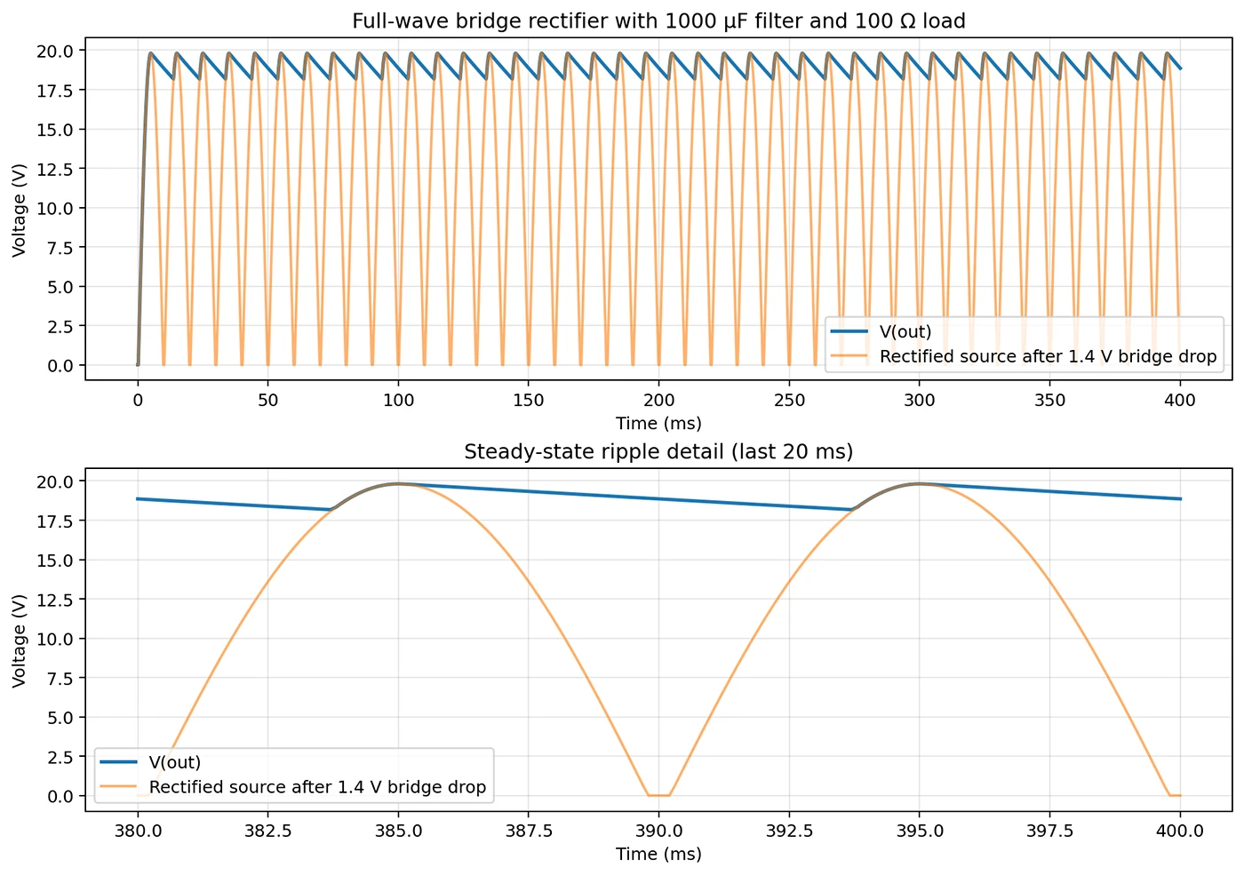
Measure ripple across rectifier circuits, filter stages, and switching approximations. Compare ripple across different capacitor values without rebuilding the test bench every time.
Try it: "Simulate a full-wave bridge rectifier using 0.7V-per-diode bridge model, with a 15 V RMS 50 Hz AC source, a 1000 µF filter capacitor, and a 100 Ω load. Report the average DC voltage, ripple frequency, and peak-to-peak ripple voltage."
Try this prompt
The simulator is powerful, and a little context on how it works helps you get more out of it.
It runs on industry-standard SPICE. Under the hood, Flux uses a proven SPICE engine with access to a verified component library of 340,000+ models. When you request a simulation, Flux interprets your request, constructs the netlist, configures sources and analysis parameters, executes the simulation, and returns results with clear explanations.
Component models matter. Flux draws from its verified model library automatically, but here's what happens at the edges:
It's conversational, not one-shot. Think of simulation in Flux as a back-and-forth. If the first result isn't quite right, adjust parameters, zoom in on a range, or ask for a different visualization. The iteration is the workflow, not a sign that something went wrong.
Start with what you know. If you have a rough idea of expected results (a ballpark cutoff frequency, a target ripple range) you'll be able to validate output quickly and course-correct.
Here's where things come together. Because simulation lives inside the same AI assistant you're already using to design, results don't just sit in a chart. They feed back into your workflow.
Ask Flux to simulate a circuit, evaluate results against your spec, and adjust component values if the numbers don't work out. Instead of hand-calculating a filter cap value and hoping for the best, you can size it based on actual simulated performance.
This works for nearly any quick validation: filter cutoffs, ripple targets, timing thresholds. Describe what "good" looks like, and let Flux iterate toward it.
The fastest way to verify a circuit is to just describe it.


A practical guide to via stitching in PCB design -- what it is, why it improves EMI, signal integrity, and thermal performance, and where to place stitching vias. Includes spacing rules (like lambda/20), design guidelines, common mistakes to avoid, and how Flux can automate stitching via placement.

A guide to PCB component selection, covering electrical specs, footprints, thermal performance, sourcing, and best practices for picking parts that ship reliably.

A guide to PCB design reviews, covering schematic, layout, and DFM checks engineers use to catch errors early and ship more reliable boards.

A guide to creating and managing PCB footprint libraries, covering IPC standards, pad sizing, validation workflows, and best practices for reliable land patterns.

A guide to PCB schematic best practices, covering organization, symbols, labeling, and readability tips for clean, maintainable circuit diagrams.

A guide to flexible PCB design, covering materials, stackups, bend radius, and layout best practices for wearables, medical devices, and other compact electronics.

A beginner-friendly guide to reading PCB schematics, covering common symbols, nets, and how to follow signal flow through a circuit diagram.

An overview of collaborative PCB design, showing how cloud-native tools, real-time editing, and shared libraries are reshaping modern hardware team workflows.
