April 20, 2023
Arduino Uno Basics: Beginner's Guide to Getting Started
Share

The word "uno" means "one" in Italian and was chosen to mark a significant redesign of the Arduino hardware and software. The Uno board was the successor of the Duemilanove release and was the 9th version in a series of USB-based Arduino boards. Version 1.0 of the Arduino IDE for the Arduino Uno board has now evolved to newer releases. The ATmega328 on the board comes preprogrammed with a bootloader that allows uploading new code without using an external hardware programmer.
While the Uno communicates using the original STK500 protocol, it differs from all preceding boards because it does not use an FTDI USB-to-UART serial chip. Instead, it uses the Atmega16U2 (Atmega8U2 up to version R2) programmed as a USB-to-serial converter. The Arduino Uno R3 board has an In-Circuit Serial Programming (ICSP) header, which provides an interface for programming the microcontroller or communicating with other devices using SPI (Serial Peripheral Interface). The ICSP header can be used to update the firmware on the board or connect additional peripherals, such as shields or breakout boards, that rely on SPI communication.
The Arduino Uno is an exceptional open-source electronics platform that empowers hobbyists and professionals alike to dive into the world of embedded systems. With its user-friendly programming language, you can easily create complex projects by writing minimal code. The Uno's powerful ATmega328P microcontroller enables rapid development of innovative applications, ranging from home automation to robotics and wearable technology to environmental monitoring. What sets the Arduino Uno apart is its compatibility with an extensive array of expansion boards (shields), enabling endless customization to suit your unique project requirements. By choosing the Arduino Uno, you're investing in a platform that has proven its versatility and reliability in countless real-world applications. Don't hesitate; embrace the Arduino Uno and unlock the limitless potential of your creative genius today.
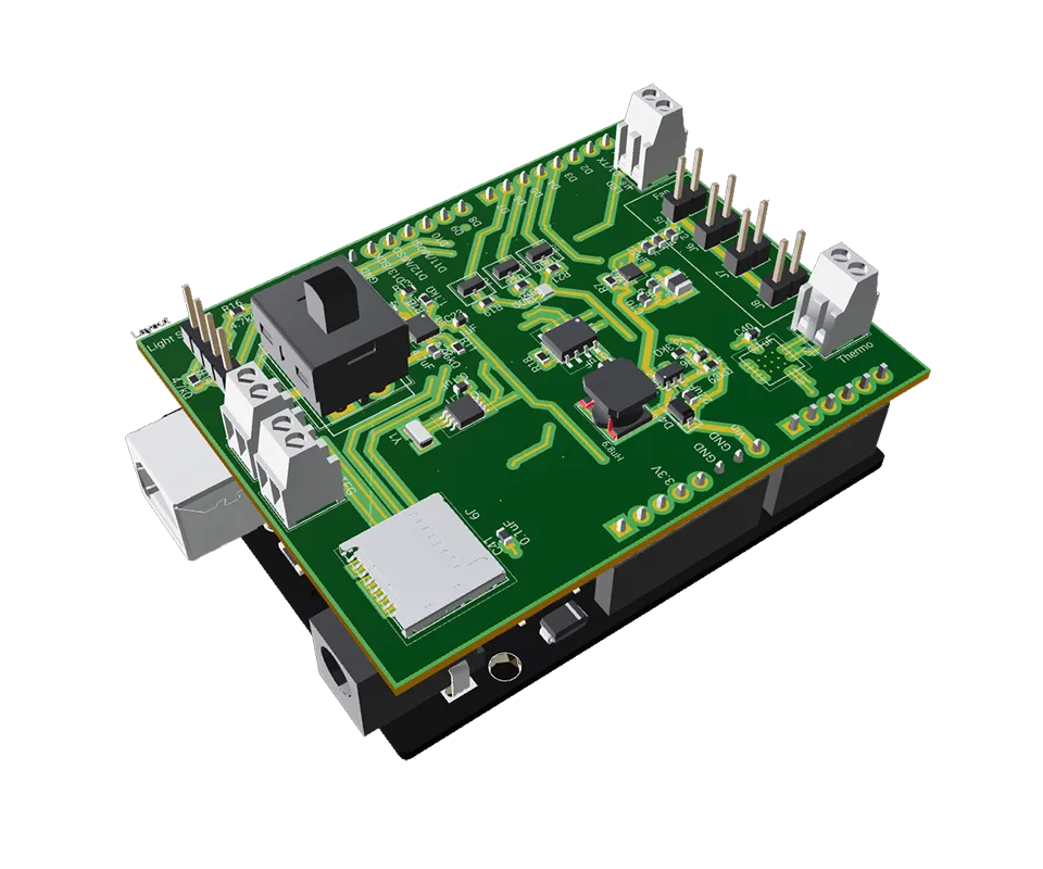
The Arduino Uno R3 is not a microcontroller itself; instead, it is a development board built around a microcontroller. The microcontroller on the Arduino Uno R3 is the ATmega328P, which is an 8-bit microcontroller from Atmel's AVR family. The board uses a USB-to-serial converter chip, which is an FTDI (Future Technology Devices International) chip on some older Arduino boards or an ATmega16U2 chip on most of the newer Arduino Uno R3 boards. The Arduino Uno R3 provides an easy-to-use platform for programming and interfacing with the ATmega328P microcontroller and various peripherals and components, making it an ideal choice for various projects.
The Arduino Uno R3 uses the ATmega328P microcontroller as its central processor. The ATmega328P is an 8-bit microcontroller from the AVR family produced by Microchip (previously Atmel). It features a 16 MHz clock speed, 32 KB of flash memory, 2 KB of SRAM, and 1 KB of EEPROM.
The Arduino Uno R3 has an ATmega328P microcontroller, which operates at a clock speed of 16 MHz. The processor can execute up to 16 million instructions per second. While this speed is relatively low compared to modern microprocessors, it is more than sufficient for most hobbyist projects and simple applications, such as sensor reading, basic automation, and simple robotics.
This table provides a comprehensive overview of the Arduino Uno R3's pinout, which can be helpful when planning and building projects using this development board. Note that some pins have multiple functions, such as digital I/O, analog input, PWM, and communication protocols like SPI and I2C.

On an Arduino board, there are three primary types of pins:
In addition to these three primary types of pins, some Arduino boards also have pins supporting communication protocols like I2C, SPI, and UART for serial communication, enabling the board to interface with various peripherals and other devices.
The Arduino Uno board has a total of 5 ground pins. Three of them are located in the power section of the board, alongside the 5V, 3.3V, and VIN pins. The other two ground pins are situated beside the digital I/O pins, specifically next to pin 13 and the AREF pin. These ground pins can be used interchangeably to provide a common reference point for the connected components and circuits.
To program an Arduino Uno R3, follow these steps:
After completing these steps, your Arduino Uno R3 should be successfully programmed and running the uploaded sketch. You can now modify the sketch or experiment with different examples to explore various functionalities and applications.
Arduino refers to both a hardware platform and an Integrated Development Environment (IDE).
The Arduino IDE and Python are related in the sense that they are both software environments used for programming, but they serve different purposes and are based on different programming languages.
The Arduino IDE supports a programming language based on both C and C++. The Arduino programming language inherits the syntax, data types, and control structures from C/C++, but it also incorporates simplified syntax and built-in functions to make it more accessible for beginners.
When you write a sketch (program) in the Arduino IDE, you can use features from both C and C++ languages, including object-oriented programming (OOP) concepts like classes and objects from C++.
Under the hood, the Arduino IDE uses the AVR-GCC compiler (for boards based on AVR microcontrollers, such as the Arduino Uno) or other appropriate compilers for different microcontroller families. These compilers support both C and C++ languages, allowing you to fully utilize the features of both languages in your Arduino sketches.

In Arduino, pinMode is a built-in function used to configure a specific digital I/O pin as either an input or an output. This function is essential for setting up the behavior of each pin on the Arduino board before using them in a sketch (program).
The pinMode function takes two arguments:
Here's the syntax for using pinMode:
Typically, you call the pinMode function in the setup() section of your Arduino sketch to configure the pin behavior before the main loop starts executing.
For example, to configure digital pin 13 as an output, you would write:
And to configure digital pin 2 as an input with an internal pull-up resistor, you would write:
Using pinMode correctly is crucial for ensuring the proper operation of your Arduino projects and avoiding potential issues with pin configurations.
Using pinMode in Arduino is necessary when working with digital I/O pins because it configures the pin behavior as either an input or an output. Properly setting the pin mode ensures that the Arduino board can interact with connected components as intended.
pinMode and digitalWrite are built-in functions in the Arduino programming language, and they serve different purposes related to digital I/O pins on an Arduino board:
Syntax: pinMode(pin, mode);
Example:
Syntax: digitalWrite(pin, value);
Example:
In summary, the pinMode function configures a digital I/O pin as either an input or an output, while the function sets the state of a digital output pin to HIGH or LOW.
The Arduino Uno R3 is a versatile, open-source microcontroller board used for a wide range of applications, including electronics projects, prototyping, learning programming and electronics, and building interactive systems. Some common uses for the Arduino Uno R3 include:
These are just a few examples of what the Arduino Uno R3 can be used for. Its simplicity, accessibility, and flexibility make it a popular choice for a wide range of applications, from beginner-level projects to more complex systems.


A practical guide to via stitching in PCB design -- what it is, why it improves EMI, signal integrity, and thermal performance, and where to place stitching vias. Includes spacing rules (like lambda/20), design guidelines, common mistakes to avoid, and how Flux can automate stitching via placement.

A guide to PCB component selection, covering electrical specs, footprints, thermal performance, sourcing, and best practices for picking parts that ship reliably.

A guide to PCB design reviews, covering schematic, layout, and DFM checks engineers use to catch errors early and ship more reliable boards.

A guide to creating and managing PCB footprint libraries, covering IPC standards, pad sizing, validation workflows, and best practices for reliable land patterns.

A guide to PCB schematic best practices, covering organization, symbols, labeling, and readability tips for clean, maintainable circuit diagrams.

A guide to flexible PCB design, covering materials, stackups, bend radius, and layout best practices for wearables, medical devices, and other compact electronics.

A beginner-friendly guide to reading PCB schematics, covering common symbols, nets, and how to follow signal flow through a circuit diagram.

An overview of collaborative PCB design, showing how cloud-native tools, real-time editing, and shared libraries are reshaping modern hardware team workflows.
