March 27, 2024
Making Parts Just Got Easier: Introducing Parametric Symbols
Share

That’s why, today, we’re introducing parametrically programmable schematic symbols in Flux.
In modern EDA tools, creating schematics and symbols entails a manual process of drawing rectangles, squares, and lines with a mouse and cursor. Too often, we fight with symbols because they’re so hard to modify. It can feel impossible to create any sort of sane signal convention. Interconnections and signal flow ultimately devolve into lines leaving your symbol’s pins in seemingly random order and direction. How is anyone supposed to make sense of these schematics?
Flux's parametric symbols change how we view schematic symbols by offering you customization and flexibility. With parametric symbols, your team can better organize your schematic symbols by grouping pins based on functionality and logical connection, without needing to physically draw the symbol. Want all GPIO to be grouped together? Maybe you want all power pins to be on the left side of the symbol? Or, do you want all ADC channel pins to be next to each other?
Parametric symbols enable your team to make designs organized and readable. The result is a symbol that isn’t just a square with some lines, it’s a neatly organized, clearly partitioned set of functions that can be easily interpreted by anyone on the team and beyond. Don’t fight with rigid symbols. Instead, organize your symbol as you want, make the signal flow clear and intuitive, and end up with a schematic design that is simple to understand.
Parametric symbols also introduce unprecedented levels of flexibility and customization. Unlike conventional symbols that need to be completely redrawn by hand if changes are desired, parametric symbols are configurable on the fly. No more hassle and wasted time using a drawing tool to rearrange pins.
At Flux, we believe your design should be declarative, not imperative. You should tell your symbols how they could behave - not the other way around. Parametric symbols are our first step in realizing this reality.
Creating parametric symbols in Flux is as simple as filling out property fields in the Inspector Panel. 4 properties determine how the symbol arranges itself:
Once the symbol is created, it can be changed easily by redefining properties to your liking. That means that symbols are dynamic and configurable with little to no effort and wasted time.
To learn more about how to work with parametric symbols in Flux, check out the documentation page.
Parametric symbols are our first step towards a truly declarative workflow with Flux. Soon, you will find declarative workflows integrated into every feature, including the PCB Editor.
Want to learn more about how to start using parametric symbols in Flux? Contact sales today.


Flux Files centralizes your project docs, assets, and AI outputs in one tab so your team and AI always have the context they need.

Whether you're migrating from popular EDA applications or starting fresh, mastering high speed PCB design has never been more intuitive. Flux enables teams to design, simulate, and route with real-time AI assistance, so you can spin your next high-speed board with total confidence.
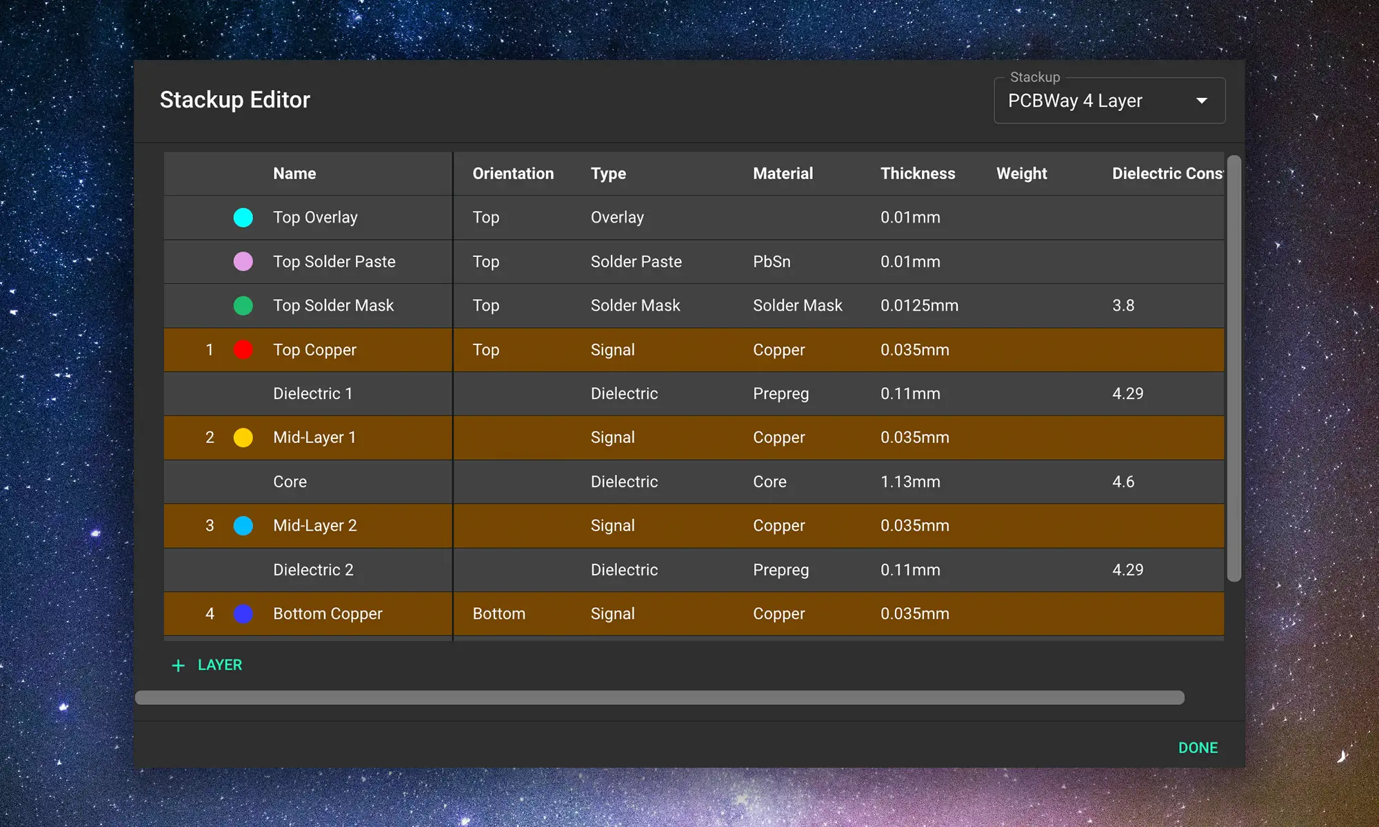
We’re launching our Stackup Editor: a new and improved way to select your PCB stackup that requires less time, less effort, and is less prone to errors. This is another massive step towards creating a single place where designers can collaborate with each other and the industry as a whole.
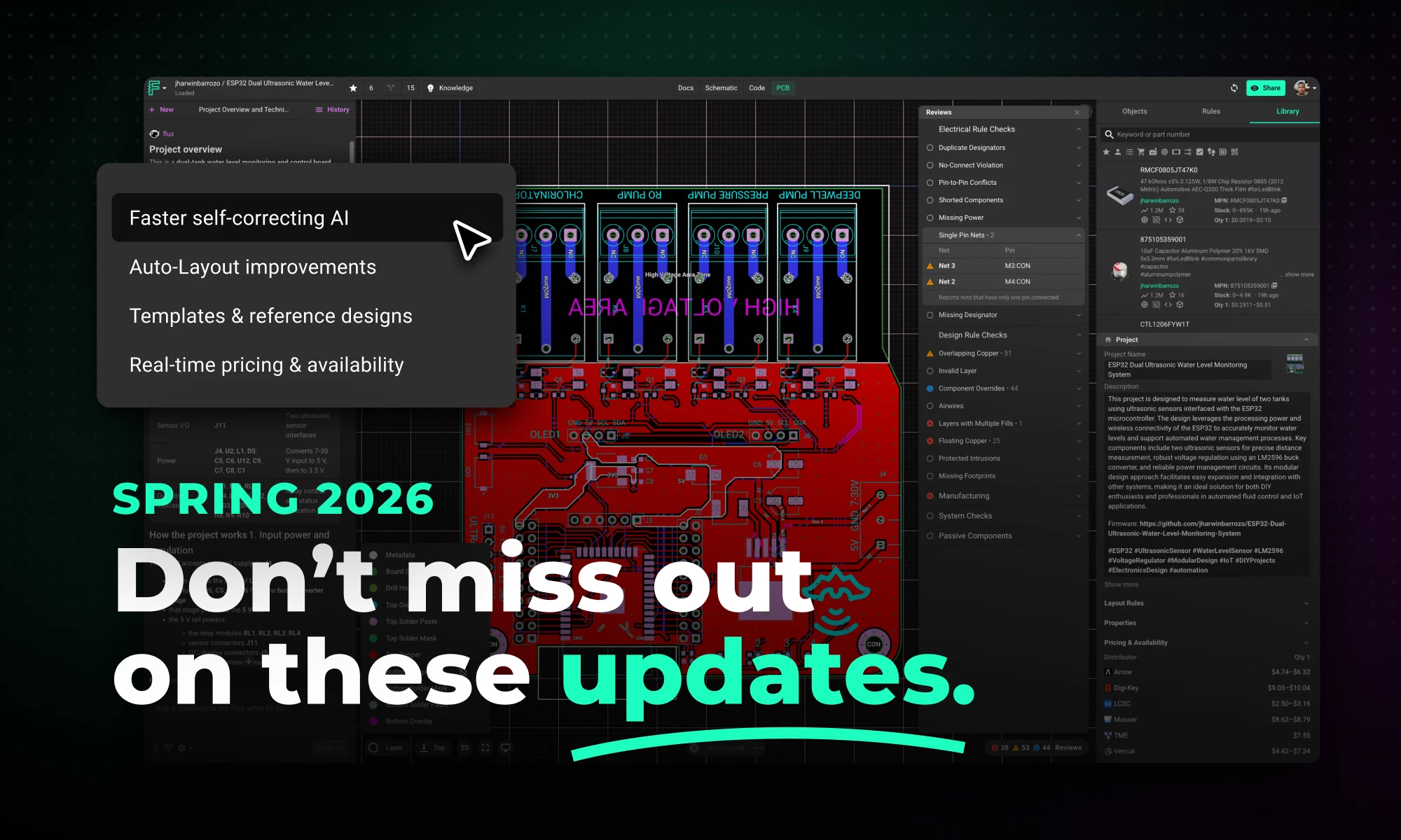
This Spring 2026 updates make hardware design faster end-to-end with a more capable, self-correcting AI agent, improved AI auto-layout that needs less cleanup, sourcing-aware design with real-time pricing and availability, and templates to start from.

This update brings more than just polish—it’s the foundation for a faster, more fluid design experience, built around the way Copilot is used today and the way we see it evolving tomorrow.

Now, Flux Copilot can learn how you work—your design principles, part selection preferences, schematic style guidelines, and testing workflows—and remember them automatically.

We're excited to unveil our Smart Polygon system in Flux! This powerful capability builds on top of our automatic copper fills to transform how you create and manage custom copper areas in your PCB designs.

Whether you’re routing high-speed buses, fine-tuning antennas, or laying out clean RF filters, sharp 90º or even 45º angles can be a serious bottleneck. Now, you can create precisely curved elbows across entire nets—or dial them in trace by trace—with full control over radius, inheritance, and overrides.

