Interface ICs
An interface IC is a type of integrated circuit that is designed to facilitate communication between two devices or systems. These devices are commonly used in electronic systems to enable the transfer of data and control signals between different components or subsystems. Some common use cases for interface ICs include connecting microcontrollers to peripherals such as sensors or displays, linking multiple processors together in a network, and enabling communication between devices using different communication protocols. Flux.ai has the world's largest community-driven public library of interface ICs, with footprints, symbols, datasheets, and simulation models. This library is a valuable resource for engineers and designers who need access to accurate and up-to-date information on these important components. Whether you are working on a new design project or simply looking to learn more about interface ICs, Flux.ai is an excellent resource to help you find the information you need.
1726040
2 Position Wire to Board Terminal Block Horizontal with Board 0.200" (5.08mm) Through Hole ## Engineering Specification ## General Description The **1726040** is a Phoenix Contact **MKKDSN series PCB terminal block** designed for wire-to-board electrical connections in printed circuit board assemblies. It is used to provide a secure screw-clamp interface between external wiring and PCB circuitry. The component is suitable for control systems, industrial electronics, power distribution circuits, automation equipment, and general electronic assemblies requiring reliable field wiring termination. ## Device Identification Manufacturer Part Number: **1726040** Manufacturer: **Phoenix Contact** Product Series: **MKKDSN** Device Category: **Connector and Interconnect Component** Device Type: **PCB Terminal Block** Connection Type: **Wire-to-Board Terminal Block** Mounting Type: **Through-Hole PCB Mount** Termination Method: **Screw Connection** ## Functional Description The device functions as a fixed printed circuit board terminal block that allows external conductors to be connected directly to a PCB. The screw-clamp mechanism secures the wire mechanically and electrically, providing a stable connection for signal or power circuits. The terminal block is intended for applications where field wiring must be removable, serviceable, and mechanically secure. ## Mechanical Description The component uses a compact green housing suitable for PCB-mounted assemblies. It is designed for side-entry conductor connection and horizontal board installation. The terminal block construction supports organized wire routing and convenient access for installation, maintenance, and service work. ## Electrical Description The terminal block is intended for low-voltage power and signal applications within the manufacturer’s specified current and voltage ratings. It provides reliable conductor contact when properly installed with compatible wire sizes and appropriate tightening torque. ## Material and Contact Description The connector housing is typically made from insulating material suitable for electrical safety and PCB assembly use. The internal conductive elements provide the electrical path between the inserted wire and the soldered PCB connection. Proper conductor preparation and screw tightening are required to maintain stable electrical performance. ## Mounting and Assembly Description The component is intended for through-hole solder mounting on a printed circuit board. Proper PCB hole sizing, pad layout, soldering process control, and mechanical clearance should be followed according to the manufacturer’s recommended design and assembly guidance. The terminal block should be mounted in a position that allows safe wire insertion and screw access. ## Application Suitability The **1726040** is suitable for industrial control boards, automation equipment, interface modules, power supply circuits, instrumentation, building control systems, relay boards, sensor wiring interfaces, and other electronic products requiring secure PCB wire termination. ## Design Considerations The design should account for wire gauge compatibility, current rating, voltage rating, tightening torque, creepage and clearance requirements, solder joint strength, and accessibility for field wiring. The terminal block should not be used beyond the manufacturer’s specified electrical, thermal, and mechanical limits. ## Hashtags #commonpartslibrary #terminalblock #pcbterminalblock #phoenixcontact #mkkdsn #wiretoboard #connector #interconnect #fixedterminalblock #screwterminal #throughholecomponent #pcbmount #industrialelectronics #automationequipment #controlsystems #powerdistribution #fieldwiring #electronicscomponents #electronicparts #hardwaredesign #pcbdesign #engineeringparts #componentlibrary #electronicsengineering
79 Uses0 Stars693022010811
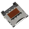
8 Position Card Connector Micro SIM Surface Mount, Right Angle Gold ## Engineering Specification ## General Description The **693022010811** is a Würth Elektronik **WR-CRD Micro SIM card connector** designed for compact electronic devices requiring secure SIM card retention and reliable board-level electrical connection. It is intended for surface-mount printed circuit board assembly and is suitable for communication modules, wireless devices, embedded systems, IoT hardware, and networking equipment. The connector uses a hinged lid mechanism to hold the Micro SIM card in place during operation. ## Device Identification Manufacturer Part Number: **693022010811** Manufacturer: **Würth Elektronik** Product Series: **WR-CRD** Device Category: **Connector and Interconnect Component** Device Type: **Micro SIM Card Connector** Connector Style: **Hinge Type** Mounting Type: **Surface Mount, Right Angle** ## Functional Description The device functions as a board-mounted Micro SIM card interface. It provides mechanical retention and electrical contact between the SIM card and the host printed circuit board. The hinged lid design allows the SIM card to be placed into the connector and secured during operation, helping maintain contact stability in compact electronic assemblies. ## Mechanical Description The connector is designed with a low-profile surface-mount construction suitable for space-constrained PCB layouts. It uses a hinged card-retention mechanism and is intended for horizontal or right-angle card installation. The mechanical structure supports reliable insertion, retention, and removal of the Micro SIM card during normal use. ## Electrical Description The connector is intended for signal-level SIM card interface applications. It provides multiple gold-plated contact positions for stable electrical connection between the SIM card and the host circuit. The device should be used within the manufacturer’s specified voltage, current, contact resistance, and insulation limits. ## Material and Contact Description The connector uses copper alloy contacts with gold plating for reliable signal transfer and corrosion resistance. The housing and mechanical retention structure are designed for surface-mount assembly and repeated card handling within the rated operating conditions. ## Mounting and Assembly Description The component is suitable for automated surface-mount PCB assembly. Proper land pattern design, soldering profile control, and mechanical clearance should be followed according to the manufacturer’s recommended layout and assembly guidance. The PCB design should provide stable grounding, correct pad alignment, and adequate clearance for SIM card insertion and lid operation. ## Application Suitability The **693022010811** is suitable for cellular communication devices, IoT modules, wireless routers, embedded modems, tracking systems, smart meters, industrial communication equipment, portable electronics, and other products requiring a Micro SIM card interface. ## Design Considerations The connector should be placed in an accessible area of the PCB to allow SIM card installation and removal. Designers should avoid excessive mechanical stress on the hinged lid, improper solder joint loading, contamination of the contact area, and operation beyond the specified environmental and electrical ratings. ## Hashtags #commonpartslibrary #connector #simconnector #microsimconnector #wurthelektronik #wrcrd #cardconnector #memoryconnector #interconnect #pcbconnector #surfacemount #rightangleconnector #smtcomponent #goldplatedcontacts #embeddedhardware #iotdevices #wirelessmodules #communicationdevices #networkingequipment #pcbdesign #hardwaredesign #electronicscomponents #electronicparts #componentlibrary #engineeringparts #electronicsengineering
2 Uses0 StarsMSLPT5252AG2TR
Tactile Switch SPST-NO Top Actuated Surface Mount ## Engineering Specification ## General Description The **MSLPT5252AG2TR** is a TE Connectivity ALCOSWITCH low-profile tactile switch designed for compact electronic devices, printed circuit board assemblies, portable electronics, control panels, and user-input interface applications. It provides momentary tactile feedback when pressed and returns to its normal open state when released. The device is suitable for applications requiring a small surface-mount switch with reliable actuation, compact board footprint, and low-profile mechanical construction. ## Device Identification Manufacturer Part Number: **MSLPT5252AG2TR** Manufacturer: **TE Connectivity** Brand Series: **ALCOSWITCH** Product Family: **LPT Low-Profile Tactile Switches** Device Category: **Electromechanical Component** Device Type: **Tactile Switch** Switch Function: **Single Pole Single Throw, Normally Open** ## Functional Description The device functions as a momentary user-input switch. When the actuator is pressed, the internal contacts close and allow an electrical signal path. When the actuator is released, the switch returns to its normally open condition. This makes the component suitable for button input, menu control, reset functions, mode selection, and general human-machine interface designs. ## Mechanical Description The switch uses a compact low-profile construction with a top-actuated flush actuator. It is intended for surface-mount installation on printed circuit boards and is suitable for space-constrained designs where low height and small board area are required. ## Electrical Description The MSLPT5252AG2TR is designed for low-current DC switching applications. It should be used within the manufacturer’s specified voltage and current ratings to ensure reliable operation and long service life. The switch is intended for signal-level control applications rather than high-power load switching. ## Contact and Material Description The switch includes stainless steel contact base material with silver contact plating. This construction supports reliable contact performance for tactile input applications and helps provide stable electrical switching behavior during normal operation. ## Mounting and Assembly Description The component is supplied as a surface-mount tactile switch suitable for automated PCB assembly. Proper land pattern design, soldering profile control, and mechanical clearance should be followed according to the manufacturer’s recommended layout and assembly guidelines. ## Application Suitability The device is suitable for portable electronic devices, consumer electronics, handheld equipment, control buttons, reset switches, interface panels, communication devices, instrumentation, remote controls, and compact PCB-based user-input systems. ## Design Considerations The switch should be placed in a location that allows direct actuator access without excessive mechanical side loading. PCB layout should provide proper solder pad support and mechanical stability. The design should avoid overtravel, excessive actuation force, contamination, and use beyond the rated electrical limits. ## Hashtags #commonpartslibrary #electromechanicalcomponent #tactileswitch #pushbuttonswitch #momentaryswitch #spstswitch #normallyopen #teconnectivity #alcoswitch #mslpt5252ag2tr #lptseries #smtcomponent #surfacemount #pcbdesign #electronicscomponents #electronicparts #switchcomponent #hardwaredesign #userinterface #embeddedhardware #consumer electronics #portableelectronics #componentlibrary #engineeringparts #electronicsengineering
85 Uses0 StarsR7FA6E10F2CFM#AA0
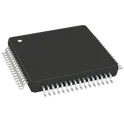
ARM® Cortex®-M33 RA6E1 Microcontroller IC 32-Bit 200MHz 1MB (1M x 8) FLASH 64-LFQFP (10x10) ## Engineering Specification ## General Description The **R7FA6E10F2CFM#AA0** is a Renesas Electronics **RA6E1 series microcontroller** designed for embedded control, industrial electronics, IoT edge devices, automation systems, and general-purpose connected applications. It is built around an **Arm Cortex-M33 processor with TrustZone support**, providing high performance, secure execution capability, and flexible integration for modern embedded designs. ## Device Identification Manufacturer Part Number: **R7FA6E10F2CFM#AA0** Manufacturer: **Renesas Electronics** Product Family: **RA Family** Series: **RA6 Series** Group: **RA6E1 Group** Device Category: **Integrated Circuit** Device Type: **Microcontroller Unit** ## Core and Processing The device uses an **Arm Cortex-M33 core** and is intended for high-performance embedded processing. It supports secure application development through TrustZone technology and is suitable for systems requiring reliable control, fast response, and efficient software execution. ## Memory Configuration The microcontroller includes program flash memory, data flash memory, and SRAM resources suitable for embedded firmware, application code, configuration storage, and runtime processing requirements. ## Package and Mechanical Description The component is supplied in an **LQFP surface-mount package**, making it suitable for compact printed circuit board layouts and standard automated assembly processes. ## Electrical and Operating Description The device is designed for low-voltage embedded systems and supports operation across an industrial temperature range. It is suitable for products requiring stable performance in controlled, commercial, or industrial operating environments. ## Communication and Interface Support The device supports common embedded communication interfaces such as USB, UART, SPI, I²C, QSPI, and CAN, allowing integration with sensors, displays, external memory, communication modules, and other peripheral devices. ## Analog and Control Features The microcontroller includes analog conversion capability, timer functions, PWM support, watchdog protection, reset monitoring, and low-voltage detection features. These functions make it suitable for control systems, monitoring equipment, and mixed-signal embedded applications. ## Security and Debug Features The device supports embedded security functions including TrustZone, unique device identification, and true random number generation. Debug and development access is supported through standard JTAG and SWD interfaces. ## Application Suitability This device is suitable for embedded controllers, IoT devices, industrial automation, metering equipment, appliance control, USB-connected products, sensor-based systems, and general electronic control applications requiring a compact and secure microcontroller solution. ## Hashtags #commonpartslibrary #integratedcircuit #microcontroller #renesas #renesaselectronics #ra6e1 #ra6series #armcortexm33 #embeddedsystems #electronicscomponents #semiconductor #mcu #iotdevices #industrialautomation #pcbdesign #electronicparts #componentlibrary #engineeringparts #hardwaredesign #electronicsengineering
0 Uses0 Stars1085
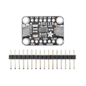
ADS1115 series 16 Bit 860 Samples per Second Analog to Digital Converter (ADC) Evaluation Board Adafruit 1085 ADS1115 Adafruit 4-Channel ADC Breakout based on Texas Instruments ADS1115 (16-bit) or ADS1015 (12-bit) analog-to-digital converter, featuring I2C communication, four single-ended inputs or two differential inputs, programmable gain amplifier (PGA) up to x16, internal voltage reference, programmable comparator, and selectable I2C addresses (0x48–0x4B). Operates from 2.0V to 5.5V and supports interfacing analog sensors with 3.3V and 5V microcontrollers such as Arduino, ESP32, STM32, RP2040, and Raspberry Pi. Search Keywords: Adafruit 4-Channel ADC Breakout, ADS1115 Breakout, ADS1015 Breakout, Adafruit ADS1115, Adafruit ADS1015, I2C ADC Module, 16-bit ADC, 12-bit ADC, 4-channel ADC, differential ADC, programmable gain amplifier, PGA ADC, analog sensor interface, TI ADS1115, TI ADS1015, Raspberry Pi ADC, Arduino ADC module, ESP32 ADC expansion Hashtags: #Adafruit #ADS1115 #ADS1015 #ADCModule #I2CADC #16BitADC #12BitADC #AnalogToDigitalConverter #SensorInterface #DifferentialADC #PGA #Arduino #ESP32 #STM32 #RP2040 #RaspberryPi #DataAcquisition #EmbeddedSystems #AdafruitBreakout
27 Uses0 StarsADPD7000BCBZR7
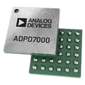
4 Channel AFE 12 Bit 36-WLCSP (2.8x2.56) The ADPD7000 is a highly integrated analog front end (AFE) designed for measuring various vital signals. The optical channel is designed as an optical transceiver, stimulating up to eight light emitting diodes (LEDs) and measuring the return signal on up to four separate current inputs. The signal chain rejects signal offsets and corruption from asynchronous modulated interference, typically from ambient light, eliminating the need for optical filters or externally controlled DC cancellation circuitry. The electrocardiography (ECG) signal acquisition is designed to support low noise, diagnostic level measurement in the presence of a variety of interferers. The ECG signal chain has a number of complementary features supporting ECG measurement, such as driven reference for common-mode rejection and lead off detection to identify a fallen electrode. The body impedance analysis (BIA) signal chain is designed for body impedance measurement with a configurable excitation path and measurement path. A 12-bit digital-to-analog converter (DAC) is used in the excitation path to generate the sinusoid wave and high precision measurement, with configurable filters used to measure the body response of the stimulus. The electrodermal activity (EDA) signal chain is designed for electrodermal activity. By multiplexing BIA and ECG peripheral circuits, the ADPD7000 supports high precision AC and DC measurement with 1 nS resolution. The data output and functional configuration use a serial port interface (SPI) on the ADPD7000. The control circuitry includes flexible LED signaling and synchronous detection, digital filters, digital wave generators, and configurable filters. The ADPD7000 is available in a 2.795 mm × 2.560 mm, 0.40 mm pitch, 36-ball WLCSP. ► Multimodal analog front end ► Optical channel ► 4 input channels with multiple operation modes for various sensor measurements ► 4-channel processing with simultaneous sampling ► 12 programmable time slots for synchronized sensor measurements ► Flexible input multiplexing to support single-ended sensor measurements ► 8 LED drivers, 2 of which can be driven simultaneously ► Flexible sampling rate from 0.004 Hz to 9 kHz using internal oscillators ► AC ambient light rejection: 78 dB up to 100 Hz ► 400 mA total LED peak drive current ► Individual ambient cancellation DAC at TIA input with 9-bit control up to 300 μA ► Individual LED DC cancellation DAC at TIA input with 7-bit control up to 190 μA ► ECG channel ► <1 µV RMS RTI noise at diagnosis bandwidth ► High input impedance 20 GΩ ► Accepts up to ±1.2 V of DC differential input range ► CMRR: 115 dB ► Flexible 4 electrode configurations to support various applications ► Both AC lead off detection and DC lead off detection ► Support always on, low power, lead on detection ► BIA channel ► Low power, high accuracy excitation path ► Configurable excitation frequency up to 250 kHz ► Sine wave excitation with a 12-bit DAC ► High accuracy with large imbalance contact impedance ≤20 kΩ ► Configurable receive filters with low noise design ► Complex impedance measurement engine ► Integrated current-limit resistors ► EDA channel ► Support both voltage excitation and current excitation ► 10 kΩ to100 MΩ measurement range with 1 nS resolution ► DFT and decimation for high accuracy measurement result ► SPI communications supported ► 704-byte FIFO
9 Uses0 StarsMIMXRT1189XVM8C
ARM® Cortex®-M33F, ARM® Cortex®-M7F RT1180 Microcontroller IC 32-Bit Dual-Core 240MHz, 800MHz 160KB (160K x 8) ROM 289-LFBGA (14x14) The MIMXRT1189XVM8C is a high-performance crossover microcontroller from the NXP Semiconductors i.MX RT1180 family, designed for advanced industrial and real-time embedded applications. It combines the real-time performance of a microcontroller with the connectivity and security features typically found in application processors. The device integrates dual Arm® Cortex® cores, high-speed networking with Time-Sensitive Networking (TSN), and advanced EdgeLock® security technology, making it ideal for industrial automation, robotics, motor control, automotive gateways, and Industry 4.0 systems. Key Features Dual-core architecture: Arm® Cortex®-M7 core running up to 800 MHz Arm® Cortex®-M33 core running up to 300 MHz Integrated Gigabit TSN Ethernet switch for deterministic real-time networking Supports industrial Ethernet protocols including: EtherCAT PROFINET Ethernet/IP CC-Link IE Advanced EdgeLock® Secure Enclave for secure boot, cryptography, and tamper detection Up to 1.5 MB on-chip SRAM with ECC protection High-speed external memory interfaces Multiple communication peripherals: CAN-FD UART SPI I2C USB Ethernet High-resolution ADCs and advanced PWM/timer modules Supports MCUXpresso SDK and Zephyr RTOS Industrial temperature range operation from -40°C to +125°C BGA package optimized for compact industrial designs #Commonpartlibrary #Microcontroller #MIMXRT1189
15 Uses0 StarsMAX2871ETJ+
Maxim Integrated PLL Frequency Synthesizer Single 23.5MHz to 6000MHz 32-Pin TQFN EP QFN-32 Maxim None MAX2871ETJ+ Unavailable Maxim Integrated MAX2871 ultra-wideband fractional-N / integer-N PLL frequency synthesizer with integrated VCOs, capable of generating RF frequencies from 23.5MHz to 6.0GHz. Features programmable output dividers (1/2/4/8/16/32/64/128), dual differential RF outputs with programmable output power from -1dBm to +8dBm, low phase noise performance, phase frequency detector up to 140MHz, reference frequency up to 210MHz, fast lock and cycle-slip reduction, automatic/manual VCO selection, on-chip temperature sensor with 7-bit ADC, 4-wire SPI-compatible serial interface, and operation from -40°C to +85°C. Suitable for wireless infrastructure, clock generation, microwave radios, RF signal generation, and test & measurement equipment. MAX2871 Search Keywords: MAX2871, Maxim MAX2871, Analog Devices MAX2871, PLL synthesizer, RF synthesizer, fractional N synthesizer, integer N synthesizer, 6GHz frequency synthesizer, RF signal generator IC, integrated VCO synthesizer, microwave synthesizer, SPI frequency synthesizer, dual output PLL, clock generation IC, wireless infrastructure synthesizer Hashtags: #MAX2871 #MaximIntegrated #AnalogDevices #PLLSynthesizer #FrequencySynthesizer #RFSynthesizer #FractionalNPLL #IntegerNPLL #IntegratedVCO #RFSignalGenerator #MicrowaveRadio #ClockGeneration #WirelessInfrastructure #SPIInterface #TestAndMeasurement #RFDesign #RFIC #PhaseLockedLoop
2 Uses0 StarsLP5816DRLR
LED Lighting Driver ICs 4-channel I2C interf ace RGBW LED driver Texas Instruments LP5816 4-channel I2C RGBW LED driver, 2.5V to 5.5V VCC range, logic input compatible with 1.8V/3.3V/5V, output voltage up to 5.5V, four high-precision constant-current sinks with 0.1mA to 51mA per channel, analog dimming and 8-bit PWM dimming up to 23kHz, 400kHz I2C interface, ultra-low power operation with 0.1µA shutdown current and 0.2mA typical active current at 25.5mA LED current, ESD protection, -40°C to +125°C operating range, available in SOT583-8 and DSBGA-8 packages. Search Keywords: LP5816, Texas Instruments LP5816, TI LP5816, LP5816 RGBW LED driver, 4 channel LED driver, I2C LED driver, RGBW LED driver IC, constant current LED driver, 51mA LED driver, 8-bit PWM LED driver, analog dimming LED driver, LP5816DLR, LP5816YCHR, SOT583-8 LED driver, DSBGA-8 LED driver Hashtags: #LP5816 #TexasInstrumentsLP5816 #TILEDDriver #RGBWLEDDriver #LEDDriverIC
1 Uses0 StarsMPU-6050
InvenSense MPU-60X0 / MPU-6000 / MPU-6050 6-axis MotionTracking IMU, integrating 3-axis gyroscope, 3-axis accelerometer and Digital Motion Processor (DMP) in a compact 4 x 4 x 0.9mm QFN package. Features programmable gyroscope ranges ±250/±500/±1000/±2000 dps, programmable accelerometer ranges ±2g/±4g/±8g/±16g, 16-bit ADCs, 1024-byte FIFO, embedded temperature sensor, I2C interface up to 400kHz and SPI interface up to 1MHz/20MHz on MPU-6000, 2.375V to 3.46V supply range, designed for motion sensing, gesture control, image stabilization, navigation, wearables, smartphones, tablets and embedded motion-control applications. Search Keywords: MPU-60X0, MPU-6000, MPU-6050, InvenSense MPU-6050, InvenSense MPU-6000, 6-axis IMU, 3-axis gyroscope accelerometer, MotionTracking sensor, Digital Motion Processor, DMP IMU, I2C IMU sensor, SPI IMU sensor, MPU6050 accelerometer gyroscope, MPU6000 gyro, QFN 4x4mm IMU, motion sensor module Hashtags: #MPU60X0 #MPU6000 #MPU6050 #InvenSenseMPU6050 #IMUSensor #6AxisIMU #Accelerometer #Gyroscope #MotionTracking #DigitalMotionProcessor #DMP #I2CSensor #SPISensor #MotionSensor #QFN24
15 Uses0 Stars