Voltage Regulators
A voltage regulator is an electronic device that maintains a constant output voltage level, regardless of changes in the input voltage or load conditions. These devices are commonly used to provide a stable power supply to electronic circuits, as well as to protect them from voltage spikes and surges. There are several types of voltage regulators, including linear, switching, and pulse width modulation (PWM) regulators, each with its own set of characteristics and applications. Linear regulators, for example, are simple and efficient, but have a relatively low switching speed and can only provide a limited output current. Switching regulators, on the other hand, have higher switching speeds and can provide a higher output current, but are more complex and require additional components. In addition to their use in power supplies and voltage protection, voltage regulators are also used in a wide range of other applications, including motor control, battery charging, and instrumentation. Flux.ai has the world's largest community-driven public library of voltage regulators, with footprints, symbols, datasheets, and simulation models for a wide range of devices. Whether you're a designer, engineer, or hobbyist, you can find the resources you need to get your project up and running quickly and efficiently.
UCS7604
UCS 76 04 Is the intelligent bad point continuous transmission series 4 channel65536, level gray scale function LED drive control special circuit, internal integratedMCU, digital interface, data latch, LED high voltage drive and other circuits. Throughthe peripheral MCU control, the separate brightness and cascade control of the chip canrealize the color dot matrix luminescence control of the outdoor large screen. Intelligent bad point continued transmission series IC adopted, advanced HPD intelligent error signal identification technology, the channel error signal identification rate reached more than 99%, and also used the patented dual decodingengine, at the same time monitoring two channels, any channel signal problem real-timeswitch. UCS 7604 RGBW channel output adopts 65535 level gray scale output, with independent current adjustment function of each channel, high precision constant currentdesign, 16K port refresh frequency, so that the picture effect more restore the real color,rich and gorgeous. Excellent product performance, stable and reliable. Double channel bad point transmission function, fault point signal can continue tobe passed down, the overall failure transmission rate of more than 99% Advanced HPD intelligent error signal identification technology, the channel faultidentification rate of more than 99% The patented dual decoding engine simultaneously monitors and decodes two channels,and any problem in the used channel will be switched to normal in real time Channel, and because it is a real-time switch, it is difficult for the human eyeto find the abnormal picture process Can work normally at any frame frequency Advanced channel fault test function, real-time dynamic light on indicates singlechannel fault and channel short circuit recessive fault in the postpartum test oflamps Grayscale level 65536,8 bit (built-in gamma 2.2, corrected to 16 bit) / 12 / 14 / 16 bitdata optional Port refresh frequency is 16K ± 5% high constant current accuracy design RGBW current per channel can be set independently The applied resistance to set the output current, 0-60 mA Data transmission frequencies of 800K / S and 1.6M / S are optional The 1 / 2 / 3 / 4 field mode is optional Chip VDD built-in 5V voltage regulator, output port pressure maximum 30V RGBW channel off, black S-AI anti-interference patented technology, which can greatly reduce and filter outradiation interference and conduction interference S-Drive drive technology and enhanced receiving technology, greatly enhance theconnection distance between points Industrial-grade design, stable and reliable #CommonPartsLibrary #IntegratedCircuit #LED-Driver #4-channel-output
2 Uses0 StarsTM1814
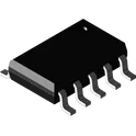
TM1814 is four channels LED constant current adjustable driver IC with function of internal control synchronizing, which can achieve a wide range of display as MCU inputs one group of data set by constant current and PWM to TM1814. When input signal is disconnected, it can realize synchronized fixation of colorful pattern change and prevent in-operation of subsequent cascade chip caused by chip damage. Internal chip is integrated with MCU solidification program and single wire digital interface, data flip-latch, LED constant current driver, circuit, etc. Internal VDD pin is integrated with 5V regulator with less peripheral devices, which applies to guardrail tube, point source and LED decorative products. This product has excellent performance and reliable quality. Features Adopt power CMOS technology Withstand voltage of OUT output port is 32V 5 V voltage-regulator tube is built into VDD, and the voltage supports 6-24 V after cascading the resistor Constant current can achieve level 64 adjustment (6.5 mA-38mA) PWM brightness controls circuit, and 256 brightness is adjustable Accurate current output value Maximum error (between channels): ±3% Maximum error (between chips): ±5% Single line serial concatenated port Oscillation mode: build in RC vibration and conduct clock synchronization according to signals on data line. After receiving the data from this unit, it can reproduce follow-up data and send it to lower level through data output end, and signals will not be distorted and reduced along with cascade Build in power on reset circuit, and after powering on reset, all registers are initialized to zero External control mode data transmission rate is 800 KHZ Internal control mode data transmission rate is 500 KHZ Internal control mode chip sends 2048 points of data Encapsulation mode: SOP8 #CommonPartsLibrary #IntegratedCircuit
0 Uses0 Stars