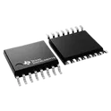
Motor Drivers
A motor driver is a device that controls the speed and direction of a motor. It takes in electrical signals and converts them into motion, allowing the motor to operate as desired. Motor drivers are commonly used in a variety of applications, including robotics, automation, and transportation systems. One company that specializes in motor drivers is Flux.ai, which has the world's largest community-driven public library of motor drivers with footprints, symbols, datasheets, and simulation models. Whether you're a professional engineer or a hobbyist, Flux.ai's comprehensive library can help you find the right motor driver for your project. With a wide range of options available, you're sure to find the perfect fit for your needs.
DRV8212DSGR
Bipolar Motor Driver NMOS On/Off, PWM 8-WSON (2x2) #DRV8212DSGR #TexasInstruments #IntegratedCircuit #MotorDriver #MotorController #BrushedDCMotorDriver #HBridgeDriver #NMOSDriver #PWMControl #PowerManagementIC #SurfaceMount #WSON8 #CategoryIntegratedCircuits #CategoryPowerManagement #CategoryMotorDriversControllers #CommonPartsLibrary
1 Uses0 StarsDRV8770RGER
Half Bridge (2) Driver DC Motors, General Purpose NMOS, Power MOSFET 24-VQFN (4x4) The DRV8770RGER is a high-voltage brushed DC motor gate driver integrated circuit manufactured by Texas Instruments, designed to drive external N-channel power MOSFETs configured in a dual half-bridge topology for use in brushed DC motor control, stepper motor drive, solenoid actuation, and other inductive load switching applications. Rather than integrating the power stage transistors directly within the IC, the DRV8770 functions as a gate driver, providing the gate voltage and current needed to fully and rapidly switch external discrete power MOSFETs, which allows the designer to choose power devices appropriate to the specific voltage and current requirements of their motor or load without being constrained by the internal power stage of an integrated motor driver. The DRV8770 delivers two half-bridge gate drivers, each capable of driving high-side and low-side N-channel power MOSFETs. The integrated bootstrap diode and external capacitor generate the correct gate drive voltages for the high-side MOSFETs, while the GVDD rail drives the gates of the low-side MOSFETs. This bootstrap architecture eliminates the need for an external isolated gate drive power supply for the high-side switch, simplifying the overall power stage design significantly compared to approaches that require separate high-side power supply generation. This device decreases system component count, reduces PCB area, and saves cost by integrating two independent half-bridge gate drivers and bootstrap diodes. digikeyTME The high-side and low-side gate drivers can drive source and sink currents sufficient for fast, efficient switching of external power MOSFETs, with total average output current capability defined in the datasheet. The asymmetric source and sink current capability is a deliberate design choice reflecting the typical requirements of power MOSFET switching, where rapid turn-off is often more critical than turn-on speed for preventing shoot-through and managing switching losses in bridge circuits. Small propagation delay and delay matching specifications minimize the dead-time requirement, which further improves efficiency. TMEFarnell The high voltage tolerance of the gate drive pins improves system robustness. The SHx phase pins can tolerate significant negative voltage transients, while the high-side gate driver supply can support higher positive voltage transients on the BSTx and GHx pins. This enhanced transient tolerance is essential in motor drive applications where inductive switching generates voltage spikes and negative voltage excursions on the switch node that would damage less robust gate driver designs. An input deglitcher prevents high-frequency noise on the input pins from affecting the output state of the gate drivers, protecting against inadvertent switching caused by electrical noise on the control interface lines. FarnellAllDataSheet The device can drive one or two DC brush motors, one stepper motor, solenoids, or other inductive loads. This versatility makes it suitable across a broad range of actuator types within the same hardware platform, allowing a single PCB design to serve multiple product variants by simply changing the connected load and the firmware control scheme. Undervoltage protection is provided for both low-side and high-side through GVDD and BST undervoltage lockout, preventing the external power MOSFETs from operating with insufficient gate drive voltage, which would cause them to enter a linear operating region with excessive power dissipation and potential thermal damage. digikeyFarnell The DRV8770RGER is housed in a compact VQFN twenty-four-pin surface-mount package, suited to space-constrained motor drive PCB layouts, and is rated for operation across an extended industrial temperature range. Spec Sheet Identification Part Number: DRV8770RGER Device Family: DRV8770 Manufacturer: Texas Instruments Functional Classification Device Type: Dual half-bridge N-channel MOSFET gate driver IC Topology: Two independent half-bridge gate drivers Application Class: Brushed DC motor, stepper motor, solenoid, and inductive load drive Gate Drive Architecture High-Side Driver: Bootstrap-based gate drive with integrated bootstrap diode Low-Side Driver: GVDD-referenced direct gate drive Gate Drive Current — Source: High source current capability for rapid MOSFET turn-on Gate Drive Current — Sink: Higher sink current capability for rapid MOSFET turn-off Voltage Ratings Maximum Operating Voltage: High-voltage class, suited to industrial motor supply rails Phase Pin Transient Tolerance: Rated for negative voltage transients on SHx switch node pins Bootstrap Pin Transient Tolerance: Elevated absolute maximum on BSTx and GHx pins for spike immunity Timing & Switching Performance Propagation Delay: Small and tightly specified for minimal dead-time requirement Delay Matching: High-side to low-side delay matching for improved bridge efficiency Input Deglitching: Built-in input deglitch filter to suppress high-frequency noise on control inputs Protection Features GVDD Undervoltage Lockout: Protects low-side gate drive from insufficient supply BST Undervoltage Lockout: Protects high-side gate drive from insufficient bootstrap voltage Negative Transient Tolerance: Phase pins rated for switch-node negative voltage excursions Load Compatibility Supported Load Types: Brushed DC motors, stepper motors, solenoids, and general inductive loads Drive Configurations: Single or dual brushed DC motor, single stepper motor, or independent half-bridge loads Environmental & Qualification Operating Temperature Range: Extended industrial temperature range RoHS Compliance: Yes Lifecycle Status: Active production Package Package Type: VQFN — Very thin Quad Flat No-Lead, twenty-four-pin Package Suffix: RGER designation Mounting Method: Surface mount technology (SMT) Package Pitch: Fine pitch, compact footprint Packaging Format Supply Format: Tape-and-reel, cut-tape, and custom reel options available #DRV8770 #DRV8770RGER #TexasInstruments #GateDriver #HalfBridgeDriver #BrushedDCMotor #MotorDriver #StepperMotorDriver #SolenoidDriver #NChannelMOSFET #BootstrapDriver #HighVoltageDriver #PowerElectronics #MotorControl #InductiveLoad #VQFN #SurfaceMount #SemiconductorIC #EngineeringSpec #ComponentLibrary #CommonPartsLibrary #RoHSCompliant #IndustrialMotorDrive
1 Uses0 StarsSTDRIVE102BP
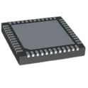
6 to 50 V, Triple half-bridge gate driver with programmable currents and SPI configuration Motor Driver NMOS SPI 48-VFQFPN (6x6) STDRIVE102BP is a highly integrated triple half-bridge gate driver designed for driving 3-phase brushless DC (BLDC) motors. It can control six external N-channel MOSFETs with programmable gate drive currents, enabling optimized switching performance and reduced EMI. The device features SPI-configurable settings, integrated charge pump circuitry for 100% high-side duty-cycle operation, built-in voltage regulators, programmable analog front-end blocks, and comprehensive protection mechanisms, making it suitable for battery-powered motor control applications such as power tools, vacuum cleaners, e-bikes, robotics, and industrial automation. Key Features Triple half-bridge gate driver for 3-phase BLDC motor control Operating supply voltage range: 6 V to 50 V Programmable gate drive capability up to: 1 A source current 2 A sink current Integrated charge pump supporting 100% high-side duty cycle Embedded 12 V LDO regulator for gate-drive circuitry Embedded 3.3 V LDO regulator for low-voltage circuitry SPI-configurable parameters and diagnostic functions Up to three programmable-gain amplifiers (PGAs) Up to three high-speed comparators VDS monitoring for MOSFET protection Thermal shutdown protection Undervoltage lockout (UVLO) protection Dual control modes (ENx/INx or INHx/INLx) TTL-compatible logic inputs up to 5 V Ultra-low standby current consumption (<50 nA) Matched propagation delay across all channels #CommonPartsLibrary #IntegratedCircuit #STDRIVE102BP #STMicroelectronics #GateDriver #BLDCMotor #MotorControl #ThreePhaseMotor #MOSFETDriver #PowerTools #Robotics #IndustrialAutomation #EBike #SPI #BrushlessMotor #EmbeddedSystems #PowerElectronics
43 Uses0 StarsULN2803ADW
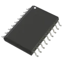
Bipolar (BJT) Transistor Array 8 NPN Darlington 50V 500mA Surface Mount 18-SOIC The ULN2803ADW is a high-voltage, high-current Darlington transistor array designed for interfacing low-level digital logic circuits with high-power loads. The device integrates eight NPN Darlington pairs with common-emitter outputs and suppression diodes for inductive load driving. It is commonly used in relay drivers, LED matrix control, solenoid actuation, motor drivers, lamp control, and industrial automation interfaces. The integrated clamp diodes enable direct driving of inductive loads without requiring additional external protection circuitry. The input stage is compatible with standard TTL and CMOS logic levels, making the device suitable for microcontroller, FPGA, and processor-based systems. The ULN2803ADW provides compact multi-channel switching capability in a wide-body SOIC surface-mount package optimized for automated assembly and high-density PCB layouts. Key Features Eight-channel NPN Darlington transistor array High-current sink driver outputs Integrated flyback suppression diodes TTL and CMOS compatible inputs Open-collector outputs Suitable for inductive and resistive loads High output voltage capability Parallel output operation supported for increased current handling Wide operating voltage range Surface-mount SOIC wide-body package Industrial and embedded control application support Electrical Characteristics Darlington transistor output configuration High DC current gain Low input current requirement Common-cathode clamp diode structure Open-collector output topology Logic-level input compatibility High-voltage output tolerance Multi-channel simultaneous switching support Applications Relay and solenoid drivers Stepper motor interfaces LED and lamp driving Industrial automation systems PLC output stages Embedded control systems Printer and actuator control Automotive electronics Logic buffer and level shifting applications Package Information Package Type: SOIC Wide Body Mounting Type: Surface Mount Multi-pin integrated driver package RoHS compliant options available #commonpartslibrary #integratedcircuit #driveric #darlingtonarray #powermanagement #industrialelectronics #embeddedhardware #relaydriver #motorcontrol #automationelectronics
82 Uses0 StarsDRV8833PWR
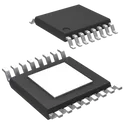
Dual-channel H-bridge motor driver The DRV8833PWR is a dual H-bridge motor driver IC from Texas Instruments designed for driving small DC motors, stepper motors, solenoids, and other inductive loads in low-voltage battery-powered systems. It integrates two full H-bridge outputs that allow independent or combined control of two motors or one bipolar stepper motor. It is commonly used in robotics, toys, printers, and embedded motion-control applications due to its compact size and built-in protection features. Key Features Dual H-Bridge Motor Driver Drives 2 DC motors independently or 1 bipolar stepper motor Wide Supply Voltage Range Operates from 2.7 V to 10.8 V motor supply (VM) Output Current Capability Up to 2 A peak per H-bridge (package-dependent RMS limits apply) Supports parallel operation for higher current drive Low On-Resistance MOSFET Output Stage Reduces power loss and improves efficiency in battery-powered designs PWM Current Regulation Built-in current limiting and chopping control for better motor performance Multiple Control Modes Forward, reverse, brake, and coast control via simple logic inputs Protection Features Overcurrent protection Short-circuit protection Undervoltage lockout (UVLO) Thermal shutdown Low-Power Sleep Mode Reduces standby current for battery applications Compact Package 16-pin TSSOP (PW package), optimized for space-constrained PCB designs #CommonPartsLibrary #IntegratedCircuit #PowerManagement
256 Uses0 Stars