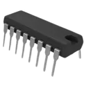
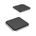
Interface ICs
An interface IC is a type of integrated circuit that is designed to facilitate communication between two devices or systems. These devices are commonly used in electronic systems to enable the transfer of data and control signals between different components or subsystems. Some common use cases for interface ICs include connecting microcontrollers to peripherals such as sensors or displays, linking multiple processors together in a network, and enabling communication between devices using different communication protocols. Flux.ai has the world's largest community-driven public library of interface ICs, with footprints, symbols, datasheets, and simulation models. This library is a valuable resource for engineers and designers who need access to accurate and up-to-date information on these important components. Whether you are working on a new design project or simply looking to learn more about interface ICs, Flux.ai is an excellent resource to help you find the information you need.
112-036-213R001
36 Position Receptacle Connector SCSI Through Hole, Right Angle Solder The 112-036-213R001 is a 36-position SCSI Centronics-style female receptacle connector designed for board-mounted I/O and high-reliability cable-to-board connections. It is part of the NorComp 112 series and is commonly used in industrial, computing, and communication equipment where rugged parallel signal interfaces are required. It features a right-angle through-hole PCB mount design with a metal shell and bail-lock mechanism to ensure secure mating and resistance to vibration and accidental disconnects. Key Features 36-position (2-row) Centronics / SCSI interface Female receptacle connector Right-angle through-hole PCB mounting Bail-lock mechanism for secure retention Outer shell / shrouded contact design Gold-plated contacts for reliable low-resistance connection 4-40 threaded flange for mechanical mounting Designed for cable-to-board I/O applications Electrical & Mechanical Highlights Number of contacts: 36 Contact arrangement: dual-row Contact finish: gold flash plating Mounting: PCB through-hole, right-angle Locking: metal bail latch system Connector type: SCSI / Centronics style I/O connector Typical Applications Industrial controllers Legacy computing / SCSI equipment Printers and scanners Measurement and test equipment High-reliability board I/O interfaces #CommonPartsLibrary #Connector
2 Uses0 Stars124018402112A
USB-C (USB TYPE-C) USB 3.2 Gen 2 (USB 3.1 Gen 2, Superspeed + (USB 3.1)) Receptacle Connector 24 Position Board Cutout, Surface Mount, Right Angle; Through Hole The 124018402112A is a surface-mount Nano SIM card connector manufactured by Amphenol. It is designed for compact mobile and embedded applications requiring a reliable Nano SIM (4FF) interface. The connector features a push-push card insertion mechanism, low-profile construction, and gold-plated contacts for improved durability and signal integrity. It is commonly used in: Cellular IoT devices LTE/5G modules GPS trackers Embedded systems Smartphones and handheld devices Industrial wireless equipment Key Features Supports Nano SIM (4FF) cards Surface-mount (SMT) package Push-push insertion/ejection mechanism Compact low-profile design Gold-plated contacts for reliable connection High durability mating cycle rating Card detect switch support Shielded metal housing Optimized for automated PCB assembly RoHS compliant Typical Electrical / Mechanical Characteristics Number of Contacts: 6-pin Nano SIM interface Mounting Type: SMT Card Type: Nano SIM (4FF) Contact Material: Copper alloy with gold plating Housing Material: High-temperature thermoplastic Operating Temperature: Industrial temperature range #CommonPartsLibrary #Connector #USB-C
2 Uses0 StarsSMAJ33A-13-F
53.3V Clamp 7.5A Ipp Tvs Diode Surface Mount SMA TVS diode SMA 33V The SMAJ33A-13-F is a surface-mount transient voltage suppression (TVS) diode designed to protect sensitive electronic components from voltage spikes and transient events. It is typically used in circuits exposed to electrostatic discharge, inductive load switching, and other transient voltage conditions. The device operates by clamping excessive voltage to a safe level, thereby preventing damage to downstream components. Its compact surface-mount package enables efficient use of board space while maintaining reliable thermal and electrical performance. Device Overview This component is constructed using silicon avalanche technology, providing fast response time to transient events. It is intended for use in high-reliability applications where overvoltage protection is critical. The unidirectional configuration ensures effective suppression in circuits with a defined polarity. The device is optimized for low leakage current under normal operating conditions and high surge capability during transient events. Electrical Characteristics The diode is designed to operate with a defined stand-off voltage, ensuring it remains non-conductive during normal system operation. Upon exceeding the breakdown threshold, the device transitions into conduction, clamping the voltage to a specified level. It supports high peak pulse power dissipation and is capable of handling repeated transient events without significant degradation. Mechanical and Packaging Information The device is provided in a compact surface-mount package suitable for automated assembly processes. The package is designed for efficient heat dissipation and mechanical robustness, supporting standard reflow soldering techniques. Terminal finishes are compatible with common PCB manufacturing processes and ensure reliable solder joints. Applications Suitable for use in consumer electronics, industrial control systems, telecommunications equipment, and automotive electronics where protection against voltage transients is required. Common use cases include power supply lines, data lines, and interface ports. Environmental and Reliability Considerations The component is designed to meet standard environmental and reliability requirements for electronic components. It is suitable for operation across a wide temperature range and is built to withstand typical handling and assembly stresses. #commonpartslibrary #circuitprotection #tvsdiode
299 Uses0 StarsMJ-63022B
6.35mm (0.250", 1/4") - Headphone Phone Jack Mono Connector Solder 6.35mm mono jack PCB The MJ-63022B is a right-angle, through-hole mounted 6.35 mm mono audio jack connector manufactured by Same Sky (formerly CUI Devices). The component is designed for PCB-mounted audio signal applications requiring a durable female phone jack interface with an internal switching mechanism. The connector supports mono audio transmission and is suitable for consumer, industrial, and embedded electronic systems where compact horizontal mounting is required. Mechanical Specification Connector type: Audio phone jack, female receptacle Audio standard: 6.35 mm (1/4 inch) mono Mounting orientation: Horizontal / right angle Mounting method: Through-hole PCB mount Number of conductors: 2 Number of contacts: 3 Internal switch configuration: Single switch / tip switch Thread size: M12 Mating depth: 31.00 mm Body color: Black Shielding: Unshielded Housing material: Polybutylene Terephthalate (PBT) Contact material: Phosphor bronze Contact plating: Silver Electrical Specification Rated voltage: 12 VDC Current rating: 1 A Signal type: Mono audio Termination type: Solder Environmental Specification Operating temperature range: -25 °C to +70 °C RoHS compliance: RoHS3 compliant REACH status: REACH unaffected Functional Features Supports standard 6.35 mm mono audio plugs Provides PCB space savings through right-angle orientation Integrated internal switch enables signal routing or detection functionality Designed for repeated insertion and removal cycles in audio applications Recommended Applications Audio amplifiers Musical instrument equipment Embedded audio systems Industrial control interfaces Consumer electronics audio input/output systems #commonpartslibrary #connector #headphone #jack
102 Uses0 StarsSTM32F407VGT6
ARM Microcontrollers - MCU ARM M4 1024 FLASH 168 Mhz 192kB SRAM 100-LQFP (14x14) Arm® Cortex®-M4 32b MCU+FPU, 210DMIPS, up to 1MB Flash/192+4KB RAM, USB OTG HS/FS, Ethernet, 17 TIMs, 3 ADCs, 15 comm. interfaces & camera • Core: Arm® 32-bit Cortex®-M4 CPU with FPU, Adaptive real-time accelerator (ART Accelerator) allowing 0-wait state execution from Flash memory, frequency up to 168 MHz, memory protection unit, 210 DMIPS/ 1.25 DMIPS/MHz (Dhrystone 2.1), and DSP instructions • Memories – Up to 1 Mbyte of Flash memory – Up to 192+4 Kbytes of SRAM including 64- Kbyte of CCM (core coupled memory) data RAM – 512 bytes of OTP memory – Flexible static memory controller supporting Compact Flash, SRAM, PSRAM, NOR and NAND memories • LCD parallel interface, 8080/6800 modes • Clock, reset and supply management – 1.8 V to 3.6 V application supply and I/Os – POR, PDR, PVD and BOR – 4-to-26 MHz crystal oscillator – Internal 16 MHz factory-trimmed RC (1% accuracy) – 32 kHz oscillator for RTC with calibration – Internal 32 kHz RC with calibration • Low-power operation – Sleep, Stop and Standby modes –VBAT supply for RTC, 20×32 bit backup registers + optional 4 KB backup SRAM • 3×12-bit, 2.4 MSPS A/D converters: up to 24 channels and 7.2 MSPS in triple interleaved mode • 2×12-bit D/A converters • General-purpose DMA: 16-stream DMA controller with FIFOs and burst support • Up to 17 timers: up to twelve 16-bit and two 32- bit timers up to 168 MHz, each with up to 4 IC/OC/PWM or pulse counter and quadrature (incremental) encoder input • Debug mode – Serial wire debug (SWD) & JTAG interfaces – Cortex-M4 Embedded Trace Macrocell™ • Up to 140 I/O ports with interrupt capability – Up to 136 fast I/Os up to 84 MHz – Up to 138 5 V-tolerant I/Os • Up to 15 communication interfaces – Up to 3 × I2C interfaces (SMBus/PMBus) – Up to 4 USARTs/2 UARTs (10.5 Mbit/s, ISO 7816 interface, LIN, IrDA, modem control) – Up to 3 SPIs (42 Mbits/s), 2 with muxed full-duplex I2S to achieve audio class accuracy via internal audio PLL or external clock – 2 × CAN interfaces (2.0B Active) – SDIO interface • Advanced connectivity – USB 2.0 full-speed device/host/OTG controller with on-chip PHY – USB 2.0 high-speed/full-speed device/host/OTG controller with dedicated DMA, on-chip full-speed PHY and ULPI – 10/100 Ethernet MAC with dedicated DMA: supports IEEE 1588v2 hardware, MII/RMII #CommonPartsLibrary #IntegratedCircuit #Microcontroller #STM32F407
62 Uses0 Stars0533981271
Connector Header Surface Mount 12 position 0.049" (1.25mm) 53398-1271 The 0533981271 is a board-to-wire connector assembly component designed to provide a reliable electrical and mechanical interface between a printed circuit board and discrete wire harnesses. It belongs to a compact connector system intended for applications requiring secure mating, efficient signal transmission, and ease of assembly. The component is engineered to support consistent electrical contact performance while maintaining a small footprint suitable for space-constrained designs. Its construction ensures dependable connectivity under typical operating conditions encountered in consumer electronics, industrial equipment, and embedded systems. Functional Description This connector component serves as part of a modular interconnect system, enabling termination of wires and subsequent mating to a corresponding board-mounted header. It provides stable retention and alignment during mating and unmating operations, ensuring consistent electrical continuity. The design supports straightforward integration into automated or manual assembly processes, facilitating efficient production workflows. Contact geometry and housing features are optimized to maintain reliable engagement and minimize the risk of intermittent connections. Electrical Characteristics The component is designed to support low-voltage signal and power transmission in compact electronic systems. It provides low contact resistance to ensure efficient current flow and stable signal integrity. Insulation materials are selected to maintain dielectric performance and prevent leakage under normal operating conditions. The connector system is suitable for typical electronic applications where consistent and reliable electrical performance is required. Mechanical Characteristics The connector features a durable housing constructed from engineered thermoplastic material, providing mechanical strength and resistance to environmental stress. Contact elements are formed from conductive alloys and finished to enhance conductivity and corrosion resistance. The design includes features that promote secure mating retention and proper alignment, reducing wear and ensuring longevity over repeated use. Its compact form factor supports high-density layouts on printed circuit boards. Environmental Characteristics The component is designed to operate reliably within standard environmental conditions encountered in electronic equipment. Materials used in the housing and contacts are selected for thermal stability and resistance to common environmental factors such as humidity and mechanical vibration. The connector system maintains performance over typical temperature ranges associated with consumer and industrial applications. Applications This connector is intended for use in electronic systems requiring compact and reliable wire-to-board interconnection. Common applications include consumer devices, industrial control systems, embedded modules, and communication equipment where dependable signal or power connectivity is essential. Summary The 0533981271 from Molex is a compact and reliable connector solution for board-to-wire applications. It offers consistent electrical performance, robust mechanical design, and ease of integration, making it well suited for modern electronic assemblies requiring dependable interconnect solutions. #commonpartslibrary #connector #header
2 Uses0 StarsFUSB340TMX
USB Switch USB 3.1 USB Interface 18-TMLP (2x2.8) The FUSB340 is a 2:1 data switch for USB SuperSpeed Gen1 and Gen2, 5 Gbps and 10 Gbps data. It is targeted at the mobile device market and for use in Type−C applications where a reversible cable requires a switch. The FUSB340 data switch offers superior performance various high speed data transmission protocols: • USB 3.1 SuperSpeed (Gen 2), 10 Gbps • PCI Express, Gen 3 • SATA • Fibre Channel • Display Port 1.3 Features • 10 GHz Typical Bandwidth • USB 3.1 SuperSpeed 5 Gbps and10 Gbps Switch • −1.0 dB Typical Insertion Loss at 2.5 GHz • Low Active Power of 12 A Typical • Low Shutdown Power of < 1 A Max. • 2 kV HBM ESD Protection • Small Packaging, 18 Lead TMLP • Wide VDD Operating Range, 1.5 V−5.0 V • This is a Pb−Free Device #CommonPartsLibrary #IntegratedCircuit #Controller #FUSB340
22 Uses0 StarsDF40HC(2.5)-50DS-0.4V(51)
50 Position Connector Receptacle, Center Strip Contacts Surface Mount Gold The DF40HC series connector is a high-density, low-profile board-to-board interconnect solution designed for compact electronic assemblies requiring reliable signal integrity and mechanical robustness. This connector is intended for parallel board stacking applications where space constraints demand minimal height and fine contact pitch. It provides secure mating with precise alignment features and is optimized for high-speed signal transmission in advanced electronic systems such as portable devices, embedded modules, and industrial electronics. Mechanical Characteristics The connector features a slim, rectangular form factor suitable for high-density PCB layouts. It incorporates a fine-pitch contact arrangement to maximize signal routing efficiency within a limited footprint. The housing is constructed from high-temperature thermoplastic material to support standard reflow soldering processes. Contacts are designed to ensure consistent normal force, enabling stable electrical connection under vibration and mechanical stress. The mating interface includes polarization features to prevent incorrect insertion and to guide proper alignment during assembly. Electrical Characteristics The connector is engineered to support reliable signal transmission across multiple contact points with low contact resistance and stable impedance characteristics. It is suitable for both signal and low-power applications. Contact plating is optimized to maintain conductivity and minimize wear over repeated mating cycles. The design supports high-speed data transfer by reducing crosstalk and maintaining signal integrity across adjacent contacts. Environmental Characteristics The component is designed to operate within standard industrial temperature ranges and is compatible with lead-free reflow soldering processes. Materials used in construction comply with common environmental and regulatory standards for electronic components. The connector maintains performance under typical environmental stresses such as humidity, temperature variation, and mechanical vibration. Materials and Finishes The insulating housing is manufactured from a high-performance thermoplastic with appropriate flammability rating. Contacts are formed from copper alloy and plated with a noble metal finish over a suitable underlayer to ensure durability, corrosion resistance, and consistent electrical performance. Application Notes This connector is intended for use in applications requiring compact stacking of printed circuit boards with reliable electrical interconnection. Proper PCB layout, including pad design and solder mask considerations, is essential to ensure optimal performance. Care should be taken during handling and assembly to avoid damage to fine-pitch contacts. Designers should follow recommended land patterns and assembly guidelines provided by the manufacturer to achieve consistent solder joints and mechanical stability. #commonpartslibrary #connector #receptacle #surfacemount
2 Uses0 StarsTPS259530DSGR
Electronic Fuse Regulator 4A 8-WSON (2x2) The TPS259530DSGR is a compact, integrated eFuse protection device designed to provide robust power-path management for low-voltage DC systems, particularly nominal five-volt rails. It combines multiple protection and control features into a single solution, enabling safe distribution of power to downstream circuitry while minimizing the need for external components. The device supports controlled inrush current during startup, continuous current monitoring, and rapid fault response to protect both the power source and the load. Integrated protection mechanisms include overvoltage protection, undervoltage lockout, overcurrent limiting, thermal shutdown, and reverse current blocking. This makes the device well suited for applications requiring high reliability, such as embedded systems, industrial electronics, consumer devices, and communication equipment. Functional Description The device operates as a high-side protection switch using an internal MOSFET to control current flow from the input supply to the load. It monitors input voltage, output current, and internal temperature to ensure operation within safe limits. When a fault condition such as overcurrent or overvoltage is detected, the device limits or interrupts current flow to prevent damage. The integrated control loop provides smooth startup by limiting inrush current and preventing supply droop. Reverse current blocking prevents unwanted current flow from the output back to the input when the input supply is removed or drops below the output level. Electrical Characteristics The device supports operation across a wide input voltage range suitable for low-voltage DC systems, including typical five-volt rails. It features an adjustable overvoltage protection threshold aligned with five-volt system requirements, along with configurable undervoltage lockout to ensure proper system startup and shutdown behavior. The current limit is externally programmable, allowing flexibility for different load conditions. The device exhibits low on-resistance to minimize power dissipation and voltage drop during normal operation. Protection Features The TPS259530DSGR integrates multiple protection functions to enhance system robustness. Overvoltage protection prevents excessive input voltage from reaching the load. Undervoltage lockout ensures the device only operates when the input supply is within a valid range. Overcurrent protection actively limits current during fault conditions and can respond rapidly to short circuits. Thermal shutdown protects the device from overheating by disabling operation when internal temperature exceeds safe limits. Reverse current blocking prevents backflow of current, safeguarding both the source and load. Control and Interface The device includes an enable control input that allows external control of the power path. It supports configurable behavior for fault response and recovery, depending on system design. External components can be used to set thresholds such as current limit and undervoltage lockout, providing design flexibility. Status signaling allows system-level monitoring of fault conditions. Mechanical and Package Information The TPS259530DSGR is provided in a compact surface-mount package suitable for space-constrained applications. The package is optimized for thermal performance and efficient PCB layout, enabling reliable operation under varying load conditions. It is supplied in tape-and-reel format for automated assembly processes. Applications This device is intended for use in systems requiring reliable power distribution and protection. Typical applications include five-volt power rails in embedded systems, industrial control modules, consumer electronics, communication devices, and peripheral power management circuits. Summary The TPS259530DSGR offers an integrated, high-reliability solution for power path protection and management in low-voltage systems. Its combination of protection features, configurability, and compact form factor makes it a widely used choice for safeguarding five-volt supply rails in modern electronic designs. #commonpartslibrary #integratedcircuit #powermanagement
1.1k Uses0 Stars